 |
| OwenDuffy.net |
|
This article describes the 144MHz horizontally polarised antenna at VK1OD in November 2008.
|
The antenna uses two identical four element arrays that were constructed around 1970. They were based on an ARRL design at the time, and we have learned a lot about Yagis since then.
The Yagis are gamma matched and each have a feedpoint impedance of around 50Ω.
An NEC model of the stacked array in free space was created and the spacing adjusted for best pattern consistent with reasonable gain. Reduction of minor lobes was a priority, part of the role of the antenna is to reject noise from the nearby TV transmitter site.
A stacking distance of 1100mm gave an optimal pattern, and a gain of just over 12dBi.
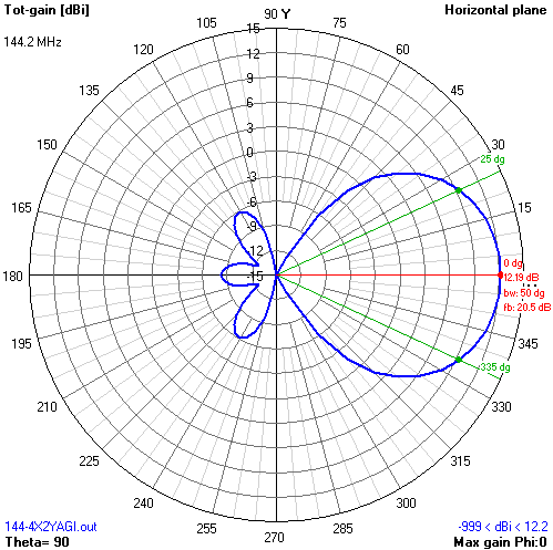 |
Fig 2 shows the modelled pattern in the horizontal plane.
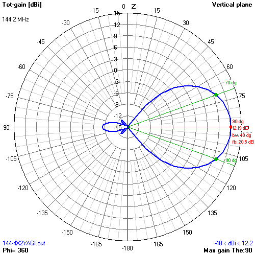 |
Fig 3 shows the modelled pattern in the vertical plane.
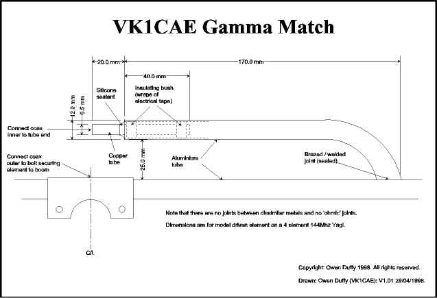 |
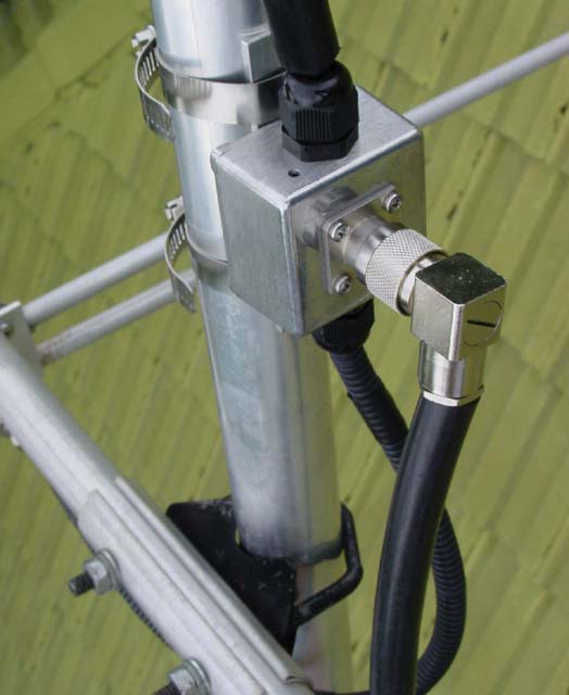
The antennas were constructed decades ago using a novel gamma match that was designed to be resistant to corrosion and ingress of water, and that has stood the test of time. Fig 4 shows the mechanical details.
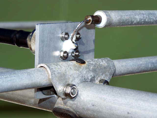 |
Fig 5 shows the matching unit on one Yagi with a new plate installed to carry an N type connector. An N type to BNC adapter is used to accept the BNC compression fitting on the end of the RG-6/U. All connectors are weatherproof.
 |
The antennas are matched with pair of transmission line transformers, the upper Yagi is fed with a three quarter wave length of RG-6/U, and the lower Yagi is fed with a one quarter wave length of RG-6/U. This creates a 180° phase difference at the feedpoints, so the lower Yagi is mounted upside down.
Whilst it is more common to use two identical matching line sections, the loss in a half wave of RG-6/U with a 50+j0Ω load at 144MHz is 0.07dB. The lower array has 1.6% more power fed to it, and modelling indicates that the affect on the pattern and gain is negligible. The phase of the drive to one array wrt the other varies with frequency, but the effect on pattern for a 2MHz bandwidth is trivial.
The odd quarter wave sections transforms the nominally 50 Ω feedpoints to about 100 Ω looking into the RG-6/U. The two RG-6/U lines are paralleled on the back of the N type connector for a nominally 50 Ω feed. Measurement at the tx shows 200mW reflected and 100W forward. The VSWR at the tx is 1.09, and accounting for line loss, is 1.12 at the antenna.
Fig 6 shows the matching interface box. It is an inexpensive die cast box with glands for the RG-6/U feedline to each array, and an N type connector for the main feedline. All feedlines are protected to prevent attach by birds.
Note that success with transmission line transformers depends on accuracy of electrical lengths, and that depends on measuring the velocity factor of the cable being used.
The Kenpro KR600 / KR600RC rotator was a recycled unit donated by VK2DO. The rotator was stripped down, cleaned, greased, tested and reassembled. A new set of upper clamps and bolts was purchased to replace a damaged clamp.
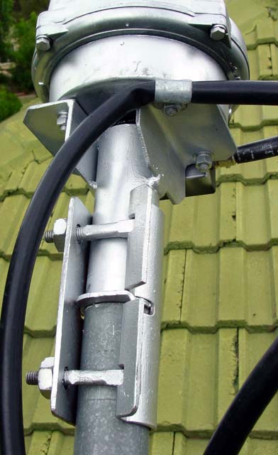 |
The antenna system is mounted atop a 6.5m length of 40mm NB gal water pipe. An adapter was fabricated from a couple of pieces of angle iron, and a short length of pipe, and a scaffold straight coupler used to connect the parts.
The rotator control cable is inserted in 13mm PE irrigation tube which seems to prevent bird attack.
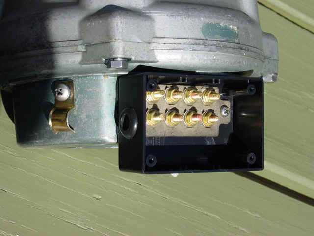 |
Fig 8 shows the reworked terminal block. The original terminal cover had been lost, and some of the pressed metal threaded inserts in the terminal block had been stripped. Short lengths of 4mm threaded brass rod were cut and soldered into the threaded inserts, and brass nuts and washers used to make the new terminal block. The terminal block was housed in a small Jiffy box and a cable gland used to protect the cable entry (not the grommet as shown in this earlier picture).
The controller exhibited erratic behavior. Most of this was caused by a dirty and oxided sliding contact in the pot. The back cover was removed, the pot cleaned, and a flexible jumper wire installed from the wiper to the middle terminal. All the terminal screws had been noodled to a greater or lesser extent. The terminal screws on the controller were replaced with new ones.
| Version | Date | Description |
| 1.01 | 08/11/2008 | Initial |
| 1.02 | ||
| 1.03 | ||
| 1.04 | ||
| 1.05 |
© Copyright: Owen Duffy 1995, 2021. All rights reserved. Disclaimer.