|
|
| OwenDuffy.net |
|
|
|
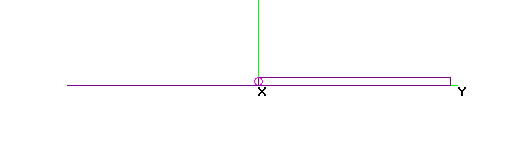
Fig 1 shows a Half Folded Dipole, the feedpoint is at the red circle
in the centre, shield connected to the lower conductor. The dipole is a
half wavelength overall, and the folded section is a quarter wave in
length.
The following analysis is for the case that all conductors are the same diameter, conductor spacing is larger than conductor diameter, and that the conductor spacing is small wrt wavelength.
The folded section is a quarter wave length long and can be regarded to be a quarter wavelength short circuited transmission line stub. A property of a quarter wavelength short circuited transmission line stub is that the differential input impedance is extremely high, and therefore the differential current adjacent to the feed point can be taken to be approximately zero.
|
|
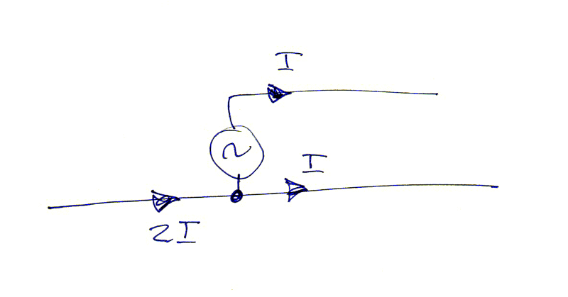
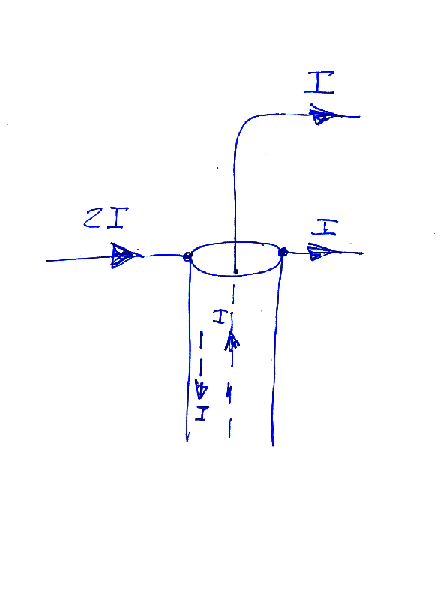
Fig 2 shows the feedpoint detail with an ideal source at the
feedpoint.
Because the differential current into the quarter wavelength short circuited transmission line stub to the right is zero, only common mode current flows, and that means that the current on the upper conductor is equal to the current on the lower conductor, both shown as I in Fig 2. Because the two conductors are very close to each other in terms of wavelength, the effect of the currents I on both conductors is almost equal to that of current 2I flowing on one conductor.
(An explanation of the concepts of differential and common mode
current is given in the article An
analysis of current
flow at
the end of
shielded twin line at radio frequencies.)
Kirchoff's Current Law (KCL) states that the sum of currents at a node is zero. By KCL, the current flowing into the node formed where the left hand side, lower right hand side, is 2I.
So, at the centre point, the configuration in Fig 2 is equivalent to a single conductor with current 2I flowing from left to right.
This configuration can be modelled in NEC.
|
|
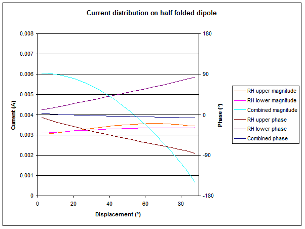
Fig 3 shows the magnitude and phase of the currents on the conductors to the right of centre.
Though the magnitude of the currents on the two right hand conductors are almost equal, and almost uniform along their length, they are not in phase with each other along the length. They start off in phase with each other and almost equal in magnitude at the feedpoint, and are almost equal to each other in magnitude but opposite in phase at the far end.
Because the upper and lower conductors are very close to each other
wrt wavelength, their combined effect is well approximated by summing
the currents in each conductor, having regard to magnitude and phase.
The 'Combined' curves in Fig 3 are the sum of the upper and lower
currents.
|
|
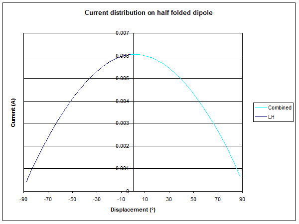
Fig 4 shows the net magnitude of the currents on the conductors of the entire antenna. The net current distribution is quite as might be expected from an ordinary half wave dipole.
Note though that the current flowing from the source is half that
which would flow if it were an ordinary dipole radiating the same
power, and therefore, the feed configuration serves as a 1:2 current
transformer, or 4:1 impedance transformer.
|
|
Fig 5 shows the feedpoint detail with coax feed.
A property of coaxial transmission line in TEM at HF and with fully developed skin effect is that the current on the outer surface of the inner conductor at any point in the line, is accompanied by an equal current in the opposite direction on the inner surface of the outer conductor. Because of this, a current I flows downwards on the inner surface of the outer conductor at the feedpoint as shown in Fig 2.
A circuit node is formed by the connection of:
At that circuit node, by KCL the net current at that node is zero, and therefore the current flowing on the outer surface of the outer conductor of the coax is 2I-I-I=0. There is not current flowing on the outer surface of the outer conductor, so a balun is not necessary to choke common mode current. Nevertheless, a common mode choke may help to minimise common mode current due to implementation imperfections.
Blonger Tongue produces antennas that use the Half Folded Half Wave Dipole, and their 1984 US Patent 4468674 shows the device in use.
The Half Folded Half Wave Dipole is used by Kent Britain (WA5VJB) in his 'Cheap Yagis'.
US Patent 6307524 names Kent Britain as the inventor of a "Yagi antenna having matching coaxial cable and driven element impedances". In that patent, he describes his "partial J folded element", that which I have referred to as a half folded half wave dipole above.
The partial folded J element used as the driven element in the present invention has an impedance of 150Ω. Therefore a compensation factor must be used when modelling the antenna design using NEC. For example, due to the 150Ω impedance of the J element, if an apparent impedance of 50Ω is desired, and impedance of 50/3Ω or approximately 17Ω should be specified in the NEC model.
I have had no difficulty in building an NEC4 model of one of Britain's 4 element "Cheap Yagi" designs for 144MHz without any fudges. The models are available for download:
When I properly create the half folded dipole driven element and feed it at the appropriate point, I get an input impedance of very close to 55+j0 at resonance, so it approximately delivers the feed point impedance that Britain promises.
When I take the same model and feed it immediately to the unfolded side of centre of the DE, I get an input impedance of very close to 12.5+j0 at resonance (though the resonance has shifted in frequency a little, differently to the NEC fudge that Britain states as necessary in his patent.
The second model suggests strongly that the half folded half wave dipole (or partial folded J element in Britain's terminology) is approximately a 4:1 transformer, certainly more so than 3:1 as claimed.
None of this is to suggest that WA5VJB Cheap Yagis don't work, they
do, just that the explanation seems inconsistent with simple theory and
NEC models.
The Half Folded Half Wave Dipole configuration is equivalent to a half wave folded dipole with an integral 4:1 impedance transformer and requiring unbalanced feed where the centre of the dipole is connected to the coax shield.
Whilst a balun is not necessary, a common mode choke may help to minimise common mode current due to implementation imperfections.
© Copyright: Owen Duffy 1995, 2021. All rights reserved. Disclaimer.