 |
| OwenDuffy.net |
|
A method sometimes used to operate on a lower band is to use a dipole that is too short as top loading for its feed line, fed against ground as a Marconi.
The dipole loaded vertical coax feed line is an evolution of the Marconi vertical. Tracing the evolutionary steps helps to understand where changes to the geometry require a different explanation of how it operates.
A quarter wave Marconi is a quite tall antenna for lower frequencies, and one method of reducing its height is to load it with a capacity hat.
|
|
Fig 1 shows the Flat Top Tee, which is a shortened vertical with horizontal wire connected to the top of the vertical wire, and the combination fed against ground. The green curves on Fig 1 are plots of the current magnitude from an NEC model of a Flat Top Tee at 3.6MHz where the horizontal wire is 22m in length and the vertical wire is 10m.
This particular combination is not resonant at 3.6MHz, the flat top happens to be a half wave on the 40m band, and the geometry is the baseline for later discussion. Using a MiniNec ground, the feed point impedance is 24+j138Ω, the low R component is to be expected for a loaded vertical, and the X component indicates it is a little longer than for resonance.
The Flat Top Tee prompts the though that perhaps a half wave dipole fed with two wire line could be operated at a capacity had loaded vertical by tying the feed line conductors together at the transmitter, and feeding them against ground.
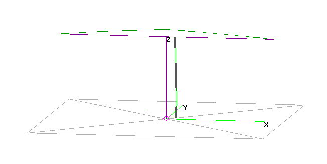 |
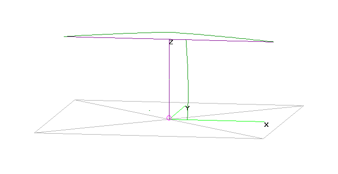
Fig 2 shows the current distribution from the NEC model. The feedpoint impedance is different to that of the Flat Top Tee, mainly because the equivalent common mode conductor formed by the two wire line is much larger than the vertical wire in the Flat Top Tee.
Note that in a perfectly symmetric implementation, the transmission line carries no differential mode current at any point, it is entirely common mode current. Bonding the conductors at the top of the open wire line makes no difference to current distribution (no current flows in the bonding link) or to feed point impedance.
The success of the dipole loaded vertical two wire feed line prompts another evolution, and that is to the dipole loaded vertical coax feed line.
The rest of this article explores the dipole loaded vertical coax feed line in detail.
Firstly, a review of the way in which coaxial cable operates.
Where coaxial cable has fully developed skin effect, and used in TEM mode (the usual mode below microwave frequencies for most practical cables), it has three conducting paths:
These three paths are isolated from each other, except at the broken end of the shield where the the inner surface of the outer conductor and the outer surface of the outer conductor effectively join. It is skin effect that effectively isolates the inner surface of the outer conductor from the outer surface of the outer conductor.
Another important property of such cables is that at any point along the cable, the current on the inner surface of the outer conductor is equal to, but opposite in direction to current on the outer surface of the inner conductor.
Practical cables are not ideal, but for most practical cables, the departure from the above is small.
For simplicity, lets consider a transmitter with coaxial output located on the ground, and its shield connection bonded directly to an effective RF ground system. The centre conductor is connected by a short single wire to the end of the coaxial cable where both inner conductor and shield are bonded.
At the top end of the coax, the shield connects to one dipole leg, and the inner conductor to the other dipole leg. There are no baluns in use.
Let us call the current on the single short wire I1, and consider that it flows in a direction away from the transmitter. Lets also designation the current on the inner conductor of the coax to be I2 (it may or may not be zero) flowing away from the transmitter. By the rules above, there is also a current of I2 flowing on the inner surface of the outer conductor towards the transmitter.
There is a node formed by the connection of the single short wire to the inner conductor, inner surface of the outer conductor and outer surface of the outer conductor. We have defined above the currents on three of the four conductors at the node, so the current on the remaining conductor, the outer surface of the outer conductor is found by Kirchoff's Current Law to be I1+I2-I2=I1 flowing away from the transmitter.
So the current flowing on the outside of the coax is the same as that on the single short wire, irrespective of any current flowing in the interior of the coax. This current gives rise to external fields, and radiation.
We have seen that there is current flowing on the outside surface of the coax. It typically forms a standing wave, so the magnitude and phase at the top end is not necessarily the same as at the bottom end, in fact they are probably different. Let us designate the current as I5 flowing towards the top end of the cable.
At the top end, the centre conductor is connected to one leg of the dipole, and let us designate the current as I6 flowing out of the cable.
At the node formed by the connection of the other dipole leg, the inner surface of the outer conductor and outer surface of the outer conductor. we have defined above, the currents on two of the three conductors, so the current on the remaining conductor, dipole leg is found by Kirchoff's Current Law to be I5-I6. This might seem to indicate a simple division of current, some of the current on the vertical coax flows into one diode leg, and the rest into the other.
No, it is not quite that simple. Whilst the current on the shield flows partially directly to one dipole leg, the balance flows around the shield end and down the inner surface of the outer conductor. There is an equal current flowing out of the inner conductor to the other dipole leg, but it is important to understand that there is current flowing inside the coax.
The current flowing inside the coax does not directly contribute to radiation, but it does give rise to conversion of some RF energy to heat in the cable, and it does result in a voltage difference across the top end of the coax, which in turn affects the current distribution on the antenna system.
An NEC model was created using RG58C/U for the vertical feed line. The feed line was modelled using an NT card to create a lossy two port network to represent 10m of RG58C/U at 3.6MHz, the NT card prototype was calculated by TLLC .
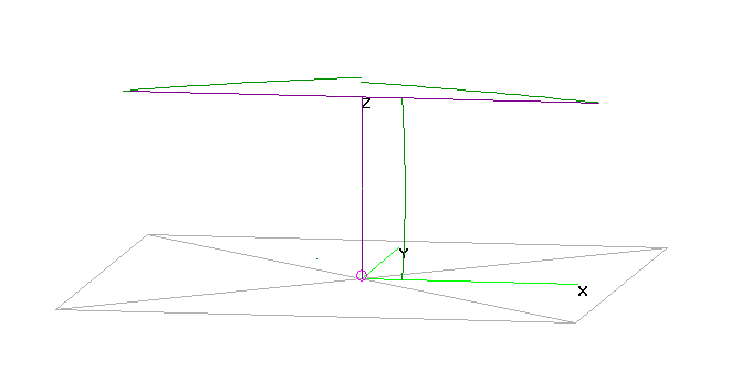 |
Fig 3 shows the current distribution from an NEC model of this configuration.
In this case, it can be seen that the current on the vertical does not divide equally into the dipole legs, and again that is due to the effect of the coax inserted in the centre of the dipole. The effect will depend on coax parameters, length and frequency.
For simplicity, lets consider a transmitter with coaxial output located on the ground, and its shield connection bonded directly to an effective RF ground system. The centre conductor is connected by a short single wire to the shield at the end of the coaxial cable, the coax inner conductor has no connection.
At the top end of the coax, the shield connects to one dipole leg, and the inner conductor to the other dipole leg. There are no baluns in use.
Let us call the current on the single short wire I1, and consider that it flows in a direction away from the transmitter. Lets also designation the current on the inner conductor of the coax to be I2 (it may or may not be zero) flowing away from the transmitter. By the rules above, there is also a current of I2 flowing on the inner surface of the outer conductor towards the transmitter.
There is a node formed by the connection of the single short wire to the inner conductor, inner surface of the outer conductor and outer surface of the outer conductor. We have defined above the currents on three of the four conductors at the node, so the current on the remaining conductor, the outer surface of the outer conductor is found by Kirchoff's Current Law to be I1+I2-I2=I1 flowing away from the transmitter.
So the current flowing on the outside of the coax is the same as that on the single short wire, irrespective of any current flowing in the interior of the coax. This current gives rise to external fields, and radiation.
(The astute reader may note that I2 must be zero since the centre conductor is disconnected, but that has no bearing on the outcome for the current flowing on the outside of the sheild.)
We have seen that there is current flowing on the outside surface of the coax. It typically forms a standing wave, so the magnitude and phase at the top end is not necessarily the same as at the bottom end, in fact they are probably different. Let us designate the current as I5 flowing towards the top end of the cable.
At the top end, the centre conductor is connected to one leg of the dipole, and let us designate the current as I6 flowing out of the cable.
At the node formed by the connection of the other dipole leg, the inner surface of the outer conductor and outer surface of the outer conductor. we have defined above, the currents on two of the three conductors, so the current on the remaining conductor, dipole leg is found by Kirchoff's Current Law to be I5-I6. This might seem to indicate a simple division of current, some of the current on the vertical coax flows into one diode leg, and the rest into the other.
No, it is not quite that simple. Whilst the current on the shield flows partially directly to one dipole leg, the balance flows around the shield end and down the inner surface of the outer conductor. There is an equal current flowing out of the inner conductor to the other dipole leg, but it is important to understand that there is current flowing inside the coax.
The current flowing inside the coax does not directly contribute to radiation, but it does give rise to conversion of some RF energy to heat in the cable, and it does result in a voltage difference across the top end of the coax, which in turn affects the current distribution on the antenna system.
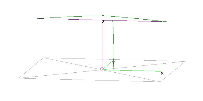 |
Fig 4 shows the current distribution from an NEC model of this configuration.
Though it might appear that the current on the vertical divides equally into the dipole legs, the division is not exactly 50%, and that is due to the effect of the coax inserted in the centre of the dipole. The effect will depend on coax parameters, length and frequency.
For simplicity, lets consider a transmitter with coaxial output located on the ground, and its shield connection bonded directly to an effective RF ground system. The centre conductor is connected by a short single wire to the inner conduct at the end of the coaxial cable, the coax shield conductor has no connection.
At the top end of the coax, the shield connects to one dipole leg, and the inner conductor to the other dipole leg. There are no baluns in use.
Let us call the current on the single short wire I1, and consider that it flows in a direction away from the transmitter. Since the wire is connected only to the coax inner conductor, there is also I1 flowing in to the coax on the inner conductor. By the rules above, there is also a current of I1 flowing on the inner surface of the outer conductor towards the transmitter.
There is a node formed by the connection of the inner surface of the outer conductor and outer surface of the outer conductor at the end of the shield. We have defined above the currents on one of the two conductors at the node, so the current on the remaining conductor, the outer surface of the outer conductor is found by Kirchoff's Current Law to be I1 flowing away from the transmitter.
So the current flowing on the outside of the coax is the same as that on the single short wire, irrespective of any current flowing in the interior of the coax. This current gives rise to external fields, and radiation.
We have seen that there is current flowing on the outside surface of the coax. It typically forms a standing wave, so the magnitude and phase at the top end is not necessarily the same as at the bottom end, in fact they are probably different. Let us designate the current as I5 flowing towards the top end of the cable.
At the top end, the centre conductor is connected to one leg of the dipole, and let us designate the current as I6 flowing out of the cable.
At the node formed by the connection of the other dipole leg, the inner surface of the outer conductor and outer surface of the outer conductor. we have defined above, the currents on two of the three conductors, so the current on the remaining conductor, dipole leg is found by Kirchoff's Current Law to be I5-I6. This might seem to indicate a simple division of current, some of the current on the vertical coax flows into one diode leg, and the rest into the other.
No, it is not quite that simple. Whilst the current on the shield flows partially directly to one dipole leg, the balance flows around the shield end and down the inner surface of the outer conductor. There is an equal current flowing out of the inner conductor to the other dipole leg, but it is important to understand that there is current flowing inside the coax.
The current flowing inside the coax does not directly contribute to radiation, but it does give rise to conversion of some RF energy to heat in the cable, and it does result in a voltage difference across the top end of the coax, which in turn affects the current distribution on the antenna system.
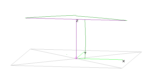 |
Fig 5 shows the current distribution from an NEC model of this configuration.
Though it might appear that the current on the vertical divides equally into the dipole legs, the division is not exactly 50%, and that is due to the effect of the coax inserted in the centre of the dipole. The effect will depend on coax parameters, length and frequency.
| Two wire line s/c at bottom both wires driven |
Coax s/c at bottom driven shield + inner |
Coax o/c at bottom driven shield |
Coax o/c at bottom driven inner |
|
| Current distribution | Fig 2 | Fig 3 | Fig 4 | Fig 5 |
| Feed point impedance (Ω) | 20.8+j62 | 27.8+j166 | 23.6+j134 | 26.5+j164 |
| Feed line loss (%) | 0.01 | 12.7 | 1.1 | 8.5 |
| impedance of coax stub | Not Applicable | 11.2+j109 | 1.3-j22.8 | Not applicable |
The impedance of the coax stub was calculated directly using TLLC , but the same results would be obtained from the Y parameters model used in the NEC NT card, if it were solved with the applicable termination (s/c, o/c).
The results in Table 1 apply to the specific model scenario, different configurations will produce different results.
The case of the dipole loaded vertical two wire feed line is quite simple. For a fully symmetric configuration (that includes that both conductors of the feed line are bonded at the bottom end), equal current flows in each conductor of the feed line and into each dipole half.
The above models and discussion give guidance to explaining how the coax feed line antennas work.
The dipole loaded vertical coax feed line is a little different. The current from the source flows onto the outside of the shield whether or not the inner conductor is bonded to the shield at the lower end. The current at the top end of the shield divides between the two dipole legs, and the coax appears as a transmission line stub in series with one of those legs.
The stub introduces an impedance that depends on the coax parameters, length, frequency and whether the bottom is s/c or o/c. This impedance alters the current distribution, and introduces a loss element.
The models show that current doesn't simply flow from the source via the centre conductor to one leg of the dipole, the division of current to each dipole leg happens at the top end of the shield.
Further, not only is it not necessary to bond the inner conductor to the shield at the lower end of the coax, it may work better if it is o/c. In the example above, the loss is lower, and the pattern is closer to that of the Flat Top Tee Marconi.
The last configuration demonstrates what most people have observed, that an antenna may work quite well at lower frequencies when the shield is not connected to the transceiver.
None of the models used for this article include metallic support elements. Vertical metal conductors will alter behaviour, especially where a metal mast was used to support the centre of the dipole, or other feed lines were bundled with the driven feed line.
Models use MiniNec ground, and do not include an allowance for ground system resistance. The R component of feed point resistance will be typically higher, depending on how good a ground system is used.
© Copyright: Owen Duffy 1995, 2021. All rights reserved. Disclaimer.