|
|
| OwenDuffy.net |
|
*** DRAFT ***
VK5AJL describes a balun at (Langsford nd) as part of his article on baluns.
|
|
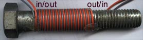
Fig 1 above is from (Langsford nd). It shows an apparently ordinary steel bolt with about 16 turns of a pair of conductors.
Langsford says:
The current balun shown here, wound around a steel bolt, is probably a little crude but why not? Steel or iron is not normally used for RF because there are too many eddys making it too inefficient for transformers. In this application, since there is no magnetic effect for the desired currents, it doesn't matter. For common mode currents on the other hand, inefficiency is an advantage. Not only is a high impedance presented to common mode currents, the energy from them is absorbed by the bolt.
He does not credit the design or idea to anyone else, or give relevant calculations or measurements to support his claims
that it is an effective current balun . He apparently understands the relevance
of common mode impedance to the task, saying [a]s soon as I have the time, I
will measure the impedance to common mode currents with various formers
. The
page has been there for some years to my knowledge, and no relevant
measurements.
(KC7DDW 2013) thinks along similar lines (or maybe he was guided by Langsford):
I tried my hand at an OCFD / Windom situation, using some plans online I first crafted a 4:1 Current balun, I used a 5/8" bolt with 9 turns of 14AWG Romex (Two Wires) I hooked the two together in the middle and then packed it in a PVC Pipe - with a few eye bolts to secure a short and long wire of stranded, insulated #14 AWG Copper wire.
A balun was made using the technique described by Langsford. No attempt has been made to duplicate his exact dimensions (which were not given), but simply to make and measure an inductor of the type he describes.
|
|
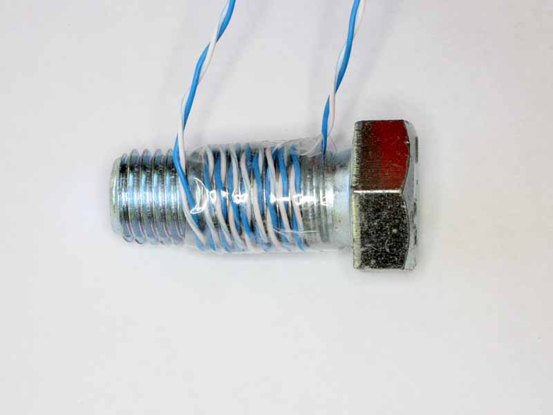
Fig 2 above shows the prototype choke. It is 10 turns of twisted pair wound close spaced onto a 16mm zinc plated mild steel bolt.
We would expect an air cored solenoid of 10 turns, 2mm pitch and 16mm diameter to have an inductance of around 1µH.
The steel core might be thought of as increasing the inductance by virtue of its relative permeability, but it is more likely that inductance will be decreased by virtue of the field due to eddy currents (ie by Lenz's law). Measurement will reveal the actual behaviour.
|
|
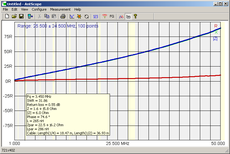
Fig 3 above shows the measured Zcm components of a the prototype VK5AJL bolt balun.
The plot shows that it behaves pretty much like an inductor in that the reactance component is fairly proportional to frequency. The Q varies from around 4 at 3.5MHz to more than 10 at 30MHz, so it is in the class of a quite low Q inductor.
But importantly, the apparent inductance is around 270nH, about a quarter of a similar solendoid without the bolt core. The Q is much lower than for a similar solendoid without the bolt core.
Any tendency to increase inductance due to the permeability of the steel core is more than offset by the effect of induced eddy current opposing the development of flux. So, in fact at HF, the bolt core does reduce inductance, and it does reduce Q.
A good current balun has a common mode impedance of thousands of ohms.
The impedance of the prototype is way too low to be effective at HF. If it was lengthened (more turns at constant pitch), the inductance will grow roughly proportionately to length, so if it was a hundred times as long, it might be effective.
The VK5AJL bolt balun is not likely to be effective, it is the product of too little knowledge and experience, and no relevant measurements to confirm the designer's propositions.
| Version | Date | Description |
| 1.01 | 14/11/2013 | Initial. |
| 1.02 | ||
| 1.03 | ||
| 1.04 | ||
| 1.05 |
© Copyright: Owen Duffy 1995, 2021. All rights reserved. Disclaimer.