 |
| OwenDuffy.net |
|
Walt Maxwell described and recommended in "Reflections II" a choke balun made by placing several ferrite sleeves around a coaxial cable.
To quote from "Reflections II": "For practical baluns to be used from 1.8 to 30 MHz (less than 12 inches long, including connector), use 50 no. 73 beads (Amidon no. FB-73-2401, or Certified Communications no. 73-W2DU.) 1 For 30 to 250 MHz, use 25 no. 43 beads (μ = 950 to 3000, Amidon no. FB-43-2401, or Certified Communications no. 43-W2DU)".
This article applies the lossy transmission line model described at A model of a practical Guanella 1:1 balun to the W2DU balun using 50 x #73 beads (FB-73-2401) over RG-303/U coaxial transmission line.
|
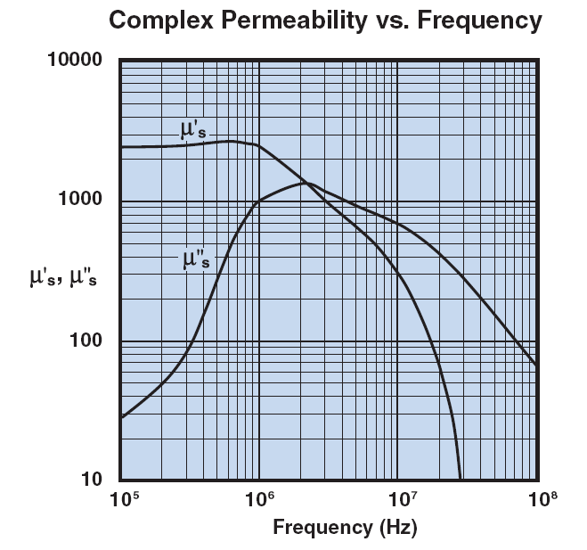
The common mode choke equivalent series resistance and inductive reactance vary with frequency. Fig 1 shows the permeability characteristics µ' and µ'' vs frequency from Fair-rite's catalogue (2673002402). Fair-rite products are resold by Amidon and possibly some of the other companies nominated in "Reflections II".
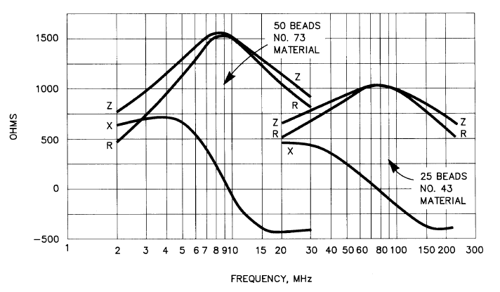 |
Fig 2 is Fig 21-3 from "Reflections II", it shows the characteristics of the common mode choke.
The curves for #73 material may seem inconsistent with Fig 1, in that the roll-off in R and Z above 9MHz are not consistent with Fig 1. The effect is probably caused by stray capacitance in W2DU's test fixture, see further discussion below.
Choke impedance Zcm=j*2*π*f*n^2*Al/µilf*(µ'-jµ'') where Al is inductance for 1 turn at µr=µilf, and µilf is the initial permeability at low frequency. This article uses the data in Fig 1.
Transmission line losses are modelled using the techniques described at RF Transmission Line Loss Calculator / Enhanced.
This section models the balun isolated from its application, it is a component characterisation rather than a model of a system containing the balun.
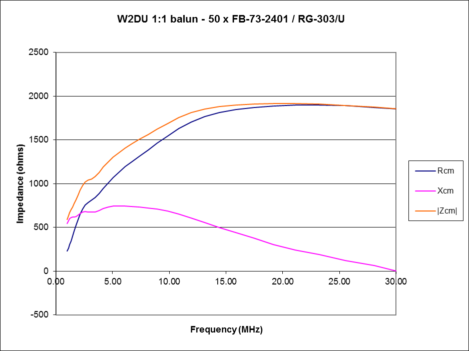 |
Fig 3 shows the common mode choke impedance for calculated from the Fair-rite catalogue. Quantity |Zcm| is the magnitude of Rcm+jXcm. The characteristic is consistent with Fig 1. As discussed earlier, W2DU's measurements are probably affected by stray capacitance, just 4pF added to the model used for Fig 3 would calibrate it to W2DU's results, but that stray capacitance would be mainly due to the test fixture and so is not included in these models.
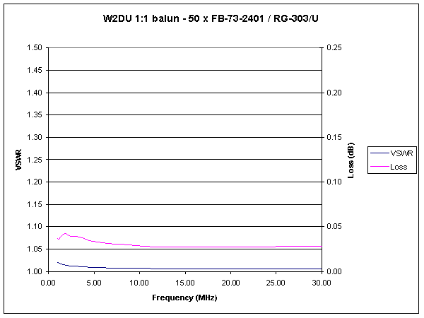 |
Fig 4 shows the VSWR and loss for the isolated balun terminated in a 50Ω load with the centre of the load grounded. The figures might look good, but this is a bench test scenario. To indicate the losses in an antenna system where coupled conductors might tend to drive feed line common mode current, the balun has to be modelled as part of an entire antenna system.
This section models an antenna system that contains the balun as an important element.
The NEC model constructed is one to contrast the apparently near ideal characteristics of the balun as an isolated component. The model is of a n 38m long dipole erected 20m above average ground and centre fed with 20m of RG-58C/U feedline from a transmitter at ground level directly underneath the feed point. The transmitter is grounded through a modest earth system with an effective RF earth resistance of 25Ω, the balun is located at the dipole feed point.
On 80m, the prime radiator is a half wave resonant dipole and losses in all components are relatively low, resulting in 80.3% of the transmitter output power being radiated.
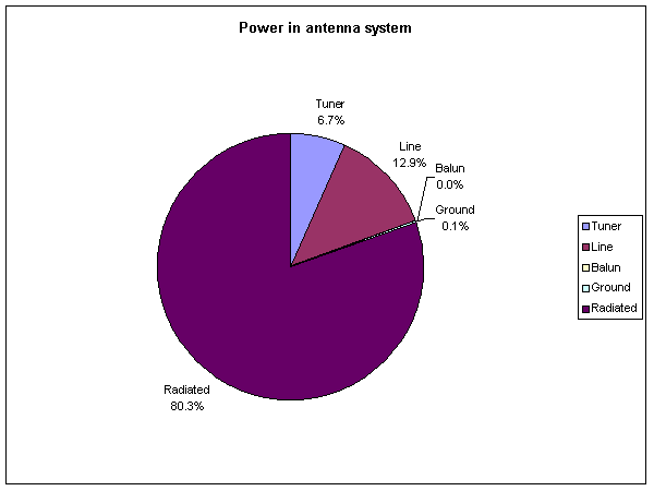 |
Fig 5 shows the distribution of input power amongst system components. This would be regarded as a practical and reasonably efficient antenna.
The efficiency of the balun itself (ie Pout/Pin) in this scenario is (80.3+0.1)/(80.3+0.1+0.0) or 100.0%, whereas the stand alone efficiency implied by Fig 1 is 99.3%.
On 40m, the prime radiator is a full wave resonant dipole and losses in most components are relatively high, resulting in just 8.6% of the transmitter output power being radiated.
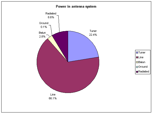 |
Fig 6 shows the distribution of input power amongst system components. This ought be regarded as a most inefficient antenna.
The key to understanding why this configuration has such high losses is to examine the current distribution on the system conductors.
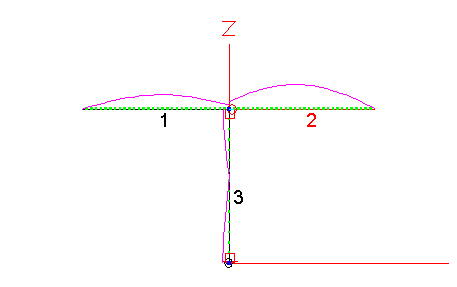 |
Fig 7 shows the current distribution on system conductors. Note the relatively high current flowing on the vertical conductor, this represents common mode current flowing on the feedline. The common mode current is the cause of the power lost in the balun and ground impedances. power is also lost in the transmission line (exacerbated by the extreme VSWR, a result of the high feed point impedance) and tuner (a result of the impedance presented by the mismatched transmission line).
Note that the balun loss is a result of the common mode current and the balun common mode impedance, and is not related to transmission line characteristic impedance. Rules of Thumb (ROT) that design a balun's common mode impedance relative only to line characteristic impedance do not consider this effect, and whilst they might be suited to lumped constant circuits, they are inadequate is assessing the effectiveness of the balun in an antenna system such as this.
If the principal objective of using the balun was to 'eliminate' common mode current entering the shack, the balun hasn't worked in this scenario.
The efficiency of the balun itself (ie Pout/Pin) in this scenario is (8.6+0.1)/(8.6+0.1+2.8) or 75.6%, whereas the stand alone efficiency implied by Fig 1 is 99.3%.
Conclusions are:
| Version | Date | Description |
| 1.01 | 08/02/2007 | Initial. |
| 1.02 | 07/03/2008 | Added stray capacitance explanation. |
| 1.03 | 11/04/2009 | Corrected small model error, added NEC model links. |
| 1.04 | ||
| 1.05 |
© Copyright: Owen Duffy 1995, 2021. All rights reserved. Disclaimer.