Crystal substitute using si5351 – part 1 described the first part of a series on an inexpensive crystal replacement using a si5351-A / MS5351M PLL chip and an ATTiny controller.

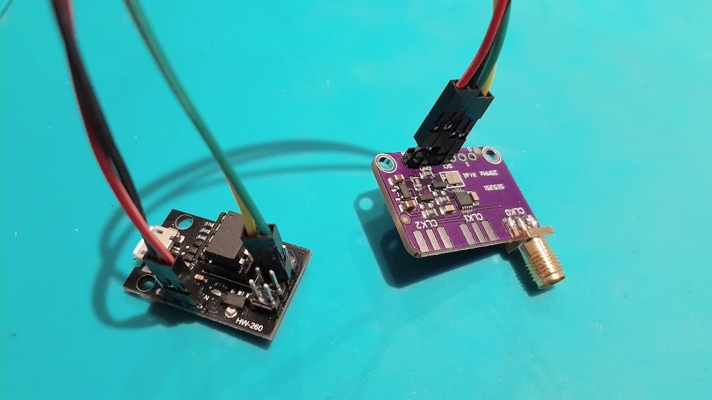
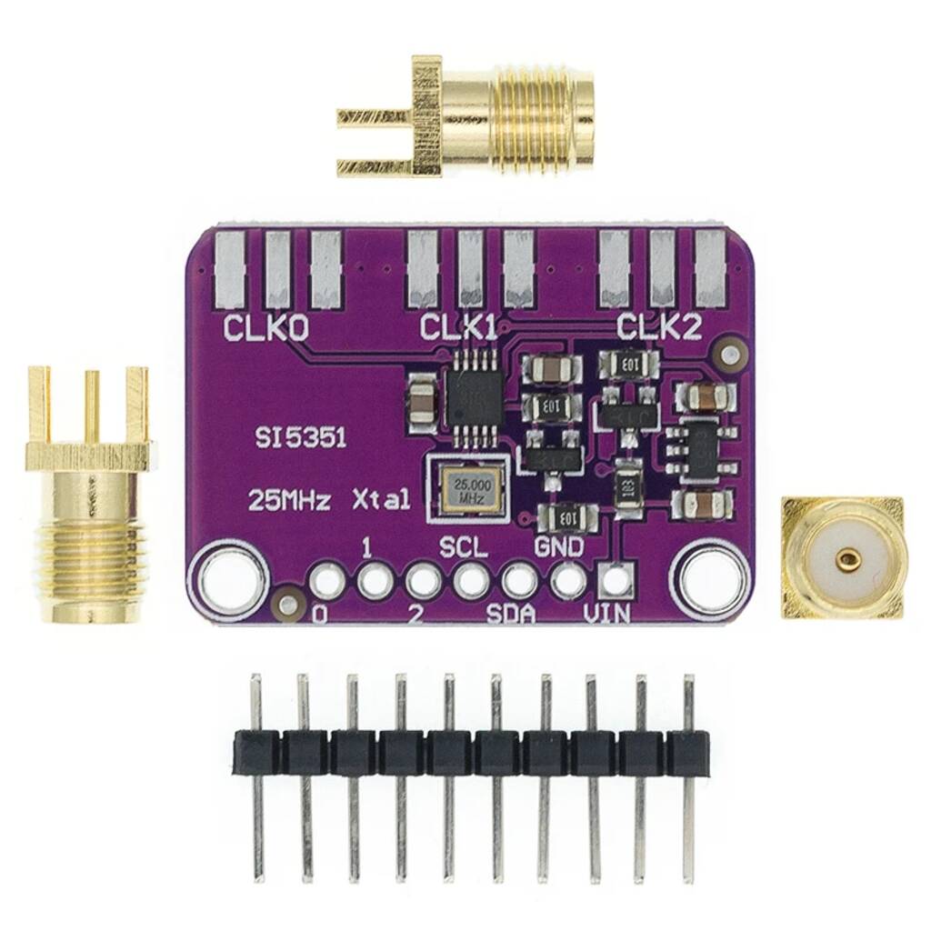
Above is an example pair of inexpensive modules, less than $10 for the pair (incl shipping). Both boards are powered from 5V, the left hand module is a ATTiny85 dev board, it has a small 3.3V regulator on board. The dev board uses a DIP chip, so it can easily be programmed in a device programmer and then inserted in the socket.

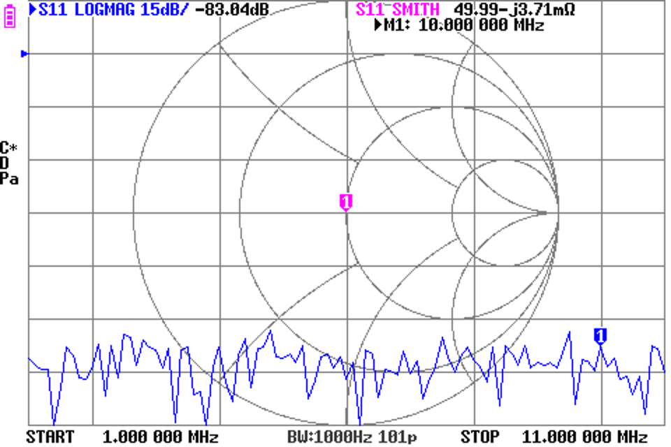
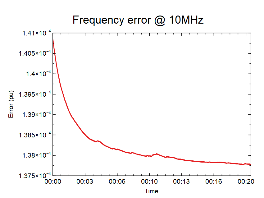
Above is a cold start of the module, error settles around +137ppm.
Development programming
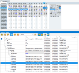
Above is a screenshot of the EEPROM configuration data with two selectable configuration sets (burstsets) programmed. The ATTinyx5 has two pins for selection of one of four burstsets, the ATTinyx4 chips have four pins available for selection one of up to 16 burstsets, limited in both cases by the EEPROM available.
Bus Pirate v5
A Python script was written to parse the exported configuration from Clockbuilder Pro and create the Bus Pirate commands to be pasted into a terminal emulator (Teraterm v5). Bus Pirate 5 is not backwards compatible with v4 and v3, so the script accepts an argument to set the language version. The script also writes a binary file of the EEPROM image for use with a device programmer.
Teraterm was used as it allow specification of a pause at the end of each line to allow Bus Pirate to execute the command.
#!/usr/bin/env python
# coding: utf-8

from pathlib import Path
import csv
import os
import sys
import struct

print('\n'+Path(__file__).stem+' v1.02 20240330 Owen Duffy\n')

import getopt,sys

def usage():
print(Path(__file__).stem+" [-a hexaddress] [-m mversion][-o outprefix][-b bfilename][-p pfilename][-t toclen] ifile1 [ifilen]...")
sys.exit(2)

try:
opts,args=getopt.getopt(sys.argv[1:],"ha:b:m:o:p:t:v:",["help","address=","bfilenane=","mversion=","outprefix=","pfilename=","toclen=","verbose="])
except getopt.GetoptError as err:
# print help information and exit:
print(err) # will print something like "option -a not recognized"
usage()
sys.exit(2)

verbose=False

ifilesn=0
ifilenames=[]
if len(args)<1:
usage()
for arg in args:
ifilenames.append(arg)
print(arg,ifilesn)
ifilesn=ifilesn+1
chip=0xc0
toclen=ifilesn+3

p=Path(ifilenames[0])
pfilename=p.with_suffix('.pllldri')
bfilename=p.with_suffix('.bp')

for o, a in opts:
if o == "-v":
verbose = True
elif o in ("-h", "--help"):
usage()
sys.exit()
elif o in ("-a", "--address"):
chip=int(a,16)
elif o in ("-m", "--mversion"):
bpv=int(a)
elif o in ("-b", "--bfilename"):
bfilename=a
elif o in ("-o", "--outprefix"):
prefix=Path(a)
pfilename=prefix.with_suffix('.pllldri')
bfilename=prefix.with_suffix('.bp')
elif o in ("-p", "--pfilename"):
pfilename=a
elif o in ("-t", "--toclen"):
toclen=a
if toclen<ifilesn:
toclen=ifilesn
else:
assert False, "unhandled option"

bfile=open(bfilename,'w')
pfile=open(pfilename,'wb')
print('Writing: ',bfilename)
print('Writing: ',pfilename)

bus=0x1
lastaddr=-2

i=0
pbuf=[]
for ifilename in ifilenames:
#write pllldri eeprom image, use burst mode for speed / efficiency
toc=b''
burst=b''
pbuf.append(b'')
burstn=0
burstlen=0
burstsetlen=0

#write bus pirate commands
bfile.write(ifilenames[i])
if(bpv==5):
bfile.write(' BP5:\n\n')
bfile.write('m\n5\nn\n100k\nW\n3.3\n100\nP\ni')
else:
bfile.write(' BP4:\n\n')
bfile.write('m4 2 2 2\ne 2\nW\nP\ni')

with open(ifilename) as csvfile:
for line in csvfile:
rdr=csv.reader(csvfile)
for row in rdr:
if(len(row)>0):
if row[0].startswith("#"):
continue
addr=int(row[0])
data=int(row[1].rstrip('h'),16)
if(addr-1==lastaddr):
bfile.write(' 0x{:02x}'.format(data))
burst=burst+struct.pack('B',data)
burstlen=burstlen+1
else:
bfile.write('\n[ 0x{:02x} 0x{:02x} 0x{:02x}'.format(chip,addr,data))
if(burstlen>0):
burst=struct.pack('B',burstlen)+burst #prepend burstlen
pbuf[i]=pbuf[i]+burst #write to file buffer
burstsetlen=burstsetlen+burstlen+1
burstn=burstn+1
burst=struct.pack('BB',addr,data)
burstlen=2
#burstn=burstn+1
lastaddr=addr
# print(row)
# print('burstlen2: ',burstlen,burstn)
if(burstlen>0):
burst=struct.pack('B',burstlen)+burst #prepend burstlen
pbuf[i]=pbuf[i]+burst #write to file buffer
burstsetlen=burstsetlen+burstlen+1
burstn=burstn+1
pbuf[i]=struct.pack('BB',burstn,burstsetlen)+pbuf[i] #prepend burst list hdr
# print('burstlen2: ',burstlen,burstn)
bfile.write(' ]\np\nw\ni\n\n')

i=i+1

#write pfile header
buf=b'\x01\x03\x00'+struct.pack('B',chip)+struct.pack('B',len(pbuf))
#append toc
offs=5+toclen*2
i=0
for x in pbuf:
buf=buf+struct.pack('<H',offs) #append toc entry
offs=offs+len(x)
i=i+1
for j in range(i,toclen):
buf=buf+b'\xff\xff' #append empty toc records
#append burst sets
for x in pbuf:
buf=buf+x
pfile.write(buf)
pfile.close
bfile.close()
Above is the Python script.
HiZ> m

Mode selection
1. HiZ
2. 1-WIRE
3. UART
4. HDPLXUART
5. I2C
6. SPI
7. 2WIRE
8. LED
x. Exit
Mode > 5

Use previous settings?
I2C speed: 100kHz

y/n, x to exit (Y) > n

I2C speed
1kHz to 1000kHz
x. Exit
kHz (400kHz*) > 100k
Mode: I2C
I2C> W
Power supply
Volts (0.80V-5.00V)

Maximum current (0mA-500mA), <enter> for none
- SDA SCL - - - - - - GND
3.30V requested, closest value: 3.30V 0.0V 0.0V 0.0V 0.0V GND
100.0mA requested, closest value: 100.0mA

Power supply:Enabled
Vreg output: 3.3V, Vref/Vout pin: 3.3V, Current: 41.7mA

I2C> P
Pull-up resistors: Enabled (10K ohms @ 3.3V)
I2C> i

This device complies with part 15 of the FCC Rules. Operation is subject to the following two conditions: (1) this device may not cause harmful interference, and (2) this device must accept any interference received, including interference that may cause undesired operation.

Bus Pirate 5 REV10
Firmware main branch (2024-04-10T12:30:36Z)
RP2040 with 264KB RAM, 128Mbit FLASH
S/N: 2145260B134063E4
https://BusPirate.com/
Storage: 0.10GB (FAT16 File System)

Configuration file: Loaded
Available modes: HiZ 1-WIRE UART HDPLXUART I2C SPI 2WIRE LED
Active mode: HWI2C (speed)=(0)
Display format: Auto
Data format: 8 bits, MSB bitorder
Pull-up resistors: ON
Power supply: ON (3.3V/3.29V)
Current limit: OK (33.6mA/100.0mA)
Frequency generators: OFF

I2C> [ 0xc0 0x02 0x53 0x00 0x20
Vout: 3.29V/100.0mA max | Pull-ups: ON |
I2C START
038.3mA SDA SCL - - - - - - GND
3.3V [ 0xc0 0x07 0x00 3.2V 3.3V 3.2V 3.3V 3.3V 3.2V GND

I2C START
031.9mA0 ACK 0x07 ACK 0x00 ACK
3.3V [ 0xc0 0x0f 0x00 0x0c 0x8c 0x8c 0x8c 0x8c 0x8c 0x8c 0x8c 3.2V

I2C START
TX: 0xC0 ACK 0x0F ACK 0x00 ACK 0x0C ACK 0x8C ACK 0x8C ACK 0x8C ACK 0x8C ACK
007.0mAC ACK 0x8C ACK 0x8C ACK
3.3V [ 0xc0 0x1a 0xa4 0x3c 0x00 0x0f 0xff 0xb9 0x55 0xbc3.3V 3.3V

I2C START
TX: 0xC0 ACK 0x1A ACK 0xA4 ACK 0x3C ACK 0x00 ACK 0x0F ACK 0xFF ACK 0xB9 ACK
038.3mA5 ACK 0xBC ACK
3.3V [ 0xc0 0x2a 0x00 0x02 0x01 0x0f 0x40 0x00 0x00 0x003.3V 3.3V

I2C START
TX: 0xC0 ACK 0x2A ACK 0x00 ACK 0x02 ACK 0x01 ACK 0x0F ACK 0x40 ACK 0x00 ACK
035.6mA0 ACK 0x00 ACK
3.3V [ 0xc0 0x5a 0x00 0x003V 3.3V 3.3V 3.3V 3.3V 3.2V

I2C START
030.5mA0 ACK 0x5A ACK 0x00 ACK 0x00 ACK
3.3V [ 0xc0 0x95 0x00 0x00 0x00 0x00 0x00 0x00 0x00V 3.3V 3.3V

I2C START
TX: 0xC0 ACK 0x95 ACK 0x00 ACK 0x00 ACK 0x00 ACK 0x00 ACK 0x00 ACK 0x00 ACK
006.5mA0 ACK
3.3V [ 0xc0 0xa2 0x00 0x00 0x00 0x00 3.3V 3.3V 3.2V 3.3V

I2C START
024.4mA0 ACK 0xA2 ACK 0x00 ACK 0x00 ACK 0x00 ACK 0x00 ACK
3.3V [ 0xc0 0xb7 0x92 ] 3.3V 3.3V 3.3V 3.2V 3.3V 3.3V

I2C START
TX: 0xC0 ACK 0xB7 ACK 0x92 ACK
010.4mAP
3.3V p 3.3V 3.3V 3.3V 3.2V 3.3V 3.2V 3.3V 3.3V
Pull-up resistors: Disabled
I2C> w
Power supply: Disabled

I2C> i

This device complies with part 15 of the FCC Rules. Operation is subject to the following two conditions: (1) this device may not cause harmful interference, and (2) this device must accept any interference received, including interference that may cause undesired operation.

Bus Pirate 5 REV10
Firmware main branch (2024-04-10T12:30:36Z)
RP2040 with 264KB RAM, 128Mbit FLASH
S/N: 2145260B134063E4
https://BusPirate.com/
Storage: 0.10GB (FAT16 File System)

Configuration file: Loaded
Available modes: HiZ 1-WIRE UART HDPLXUART I2C SPI 2WIRE LED
Active mode: HWI2C (speed)=(0)
Display format: Auto
Data format: 8 bits, MSB bitorder
Pull-up resistors: OFF

Frequency generators: OFF
Above is a console log of Bus Pirate v5 programming of the PLL for development testing.
… more to follow.
Last update: 19th April, 2024, 1:16 PM