 |
| OwenDuffy.net |
|
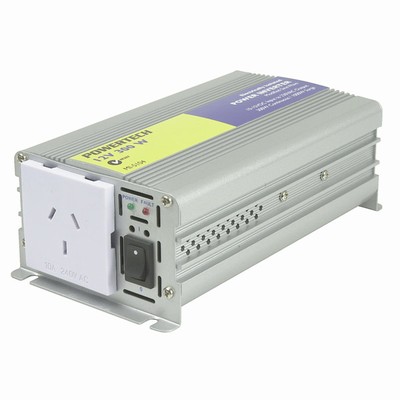
This article uses the Jaycar MI5105 inverter as an example to illustrate issues with power inverters.
|
|
The Jaycar MI5104 is a low cost inverter, described on the label as a 300W
modified sine wave inverter
.
What does "modified sine wave" mean?
Most inverters use some kind of switching technology. The very simplest approach is a symmetric square wave, but they have disadvantages for some kinds of loads and more importantly, buyers seem to be wary of square wave inverters but accepting of anything with "sine" in the description.
Modified sine wave is applied to almost anything that isn't a simple symmetric square wave, to those that the sellers represent as "true sine wave", though that description can also be very misleading.
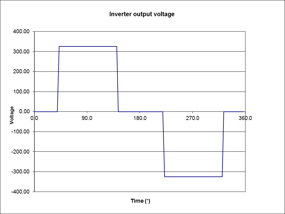 |
Fig 2 is a plot of the output voltage waveform for the inverter with no load, constructed from waveform measurement. From this waveform, the RMS voltage can be determined, and the RMS voltage for the fundamental and harmonic components.
The peak voltage is 325V, and the RMS voltage is 244V. RMS/Pk is 0.750, a little higher than the 0.707 for a perfect sine wave, and Total Harmonic Distortion is 40%.
The peak voltage is important, because for loads like a peak rectifier (as found in many switched mode power supplies), this is almost exactly the 325.3V you expect from a harmonised nominal 230V sine wave supply.
This RMS value of the complex waveform could be used to calculate the power delivered to a purely resistive load such as a simple heating element, and this supply will heat a resistor load just a little more ()9%) than a harmonised nominal 230V sine wave supply. This parameter is critically important for incandescent lighting where light output and lamp life is very dependent on the waveform RMS voltage.
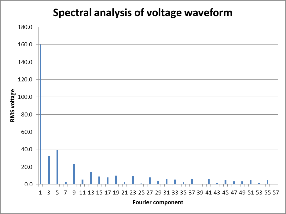 |
The voltage waveform contains a substantial component at 50Hz, but is also rich in harmonic content. Fig 3 shows the RMS value of the frequency components. The switching action gives rise to potential for significant harmonic content through to radio frequencies and RFI is a risk of all of the switching technologies, though effective filtering may reduce emissions to acceptable levels.
The first notable point is that the 50Hz component is only 160V RMS. If we have a load that utilises predominantly the 50Hz component, then the power developed in the load may be as little as 48% of that available from a 230V sine wave.
So, what type of loads could fall into this category?
The current that flows in an induction motor at full load is a predominantly a function of the rotor resistance, slip and the combination of stator leakage reactance and rotor inductance. When an induction motor slows under load, more current flows through this series path of an equivalent R and X. When powered from a source like this inverter, harmonic currents will be lower due to the higher leakage reactance plus much higher rotor reactance at the much higher rotor frequency, and those currents might not assist torque in a significant way. So, the motor performance is degraded in a way similar to that of running on 160V RMS, which will reduce to power available, or alternatively reduce efficiency and possibly overheat the motor if it is loaded to its rated power. That is not to say that you cannot run induction motors off this inverter, just they will be capable of less than rated power.
Brush motors of the universal AC/DC type as found in electric drills etc will fare better on this waveform and might give close to rated power with good efficiency. The variable speed controller in some of these tools might not work as well as on a sine wave supply.
No, it depends on the waveform and there are a wide range of waveforms used, and some vary as a function of the automatic voltage regulator built into the device.
The subject inverter obviously uses just two FETs to switch the primary of the transformer. More sophisticated designs can use four FETs for a better approximation of a sine wave, and PWM techniques provide an alternate way of creating a near sine wave, albeit using much higher switching speed which has efficiency and RFI consequences. Most PWM inverters will be categorised as "true sine wave" inverters. As always, beware of "true" in promotional use.
You might be surprised to learn that the RMS voltage of the fundamental component for an inverter with the same peak voltage is substantially higher at 207V RMS, and in an induction motor, more than 80% of rated power should be available without adverse outcomes.
It may well be that this type of inverter is a better selection for driving an induction motor load. If designed for the purpose, it is simpler, has fewer parts, develops good torque at good efficiency without stressing motor insulation unduly (Gynes et al 1977).
Square wave inverters are very hard to find nowadays, the market is mostly modified square / sine wave, and true / pure sine wave, though most do not give quantitative measure of waveform properties.
That is hard to understand, since computer power supplies typically rectify the mains directly and charge a filter capacitor. They are most sensitive to the peak voltage, so even a square wave inverter that is spike free should work fine. It is difficult to understand the claims, they may be advertising hype.
Motors have high inrush currents when the power is applied at stall. The inrush current is designed into the motor, and depends on the rotation inertial of the motor, the type of load, and the motor characteristics. It can easily be 10 times the rated load current, so if you have a motor rated at 300VA, the inverter may need to supply 3000VA / 2000W briefly to start the motor.
If the "true" sine wave inverter produces a waveform that under all conditions is as good as the mains supply, then all appliances should work just find. The question though is whether a particular inverter achieves that, and this can only be determined by test.
As to whether it is the "best" option, that depends on the user's criteria. True sine wave inverters are more complex, more costly and often lower efficiency, so may not be the "best" option for some applications.
| Version | Date | Description |
| 1.01 | 16/01/2012 | Initial. |
| 1.02 | ||
| 1.03 |
© Copyright: Owen Duffy 1995, 2021. All rights reserved. Disclaimer.