Anatek ESR Meter - VK1OD implementation
This article describes the VK1OD implementation of the Anatek 'Blue' ESR
meter designed by Bob Parker.
The meter is designed to measure the equivalent series resistance of
electrolytic capacitors.
The meter was purchased as a kit set from the Australian distributor Trans
Electronics. The kit was complete (though some parts had different designations
to the documentation), documentation was not included, and Trans Electronics
were very slow in shipping the goods.
Fig 1:
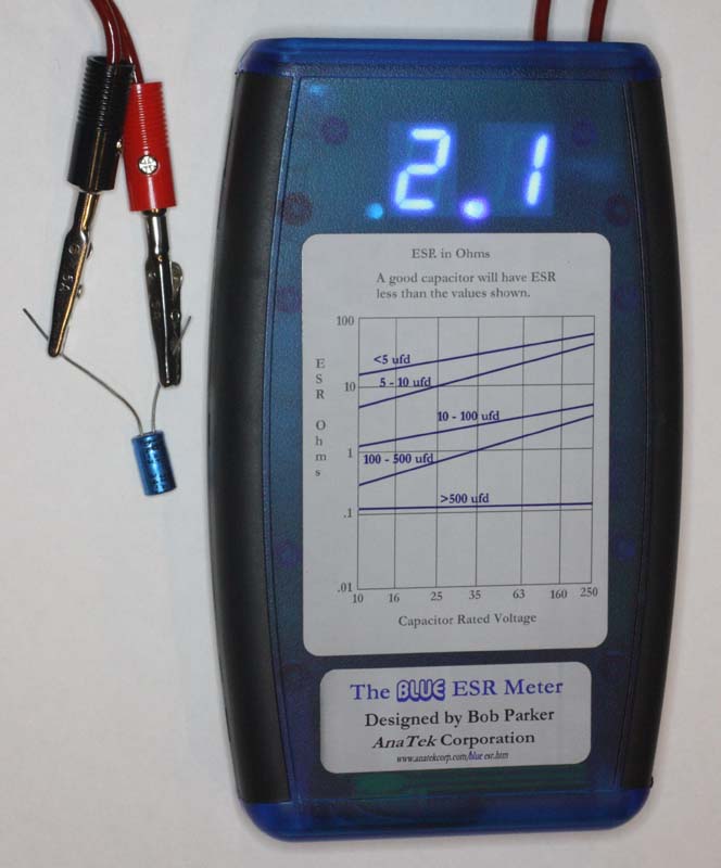 |
Fig 1 shows the ESR meter in application, measuring the ESR of an old
electrolytic capacitor.
Fig 2:
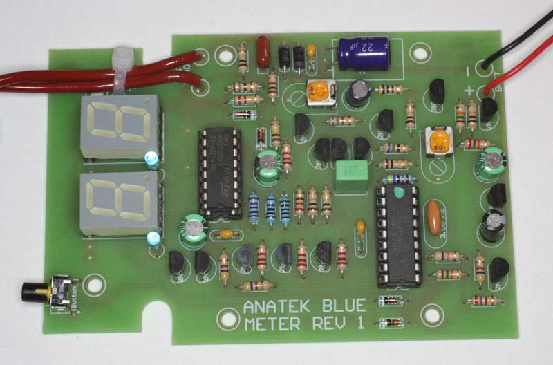 |
Fig 2 shows the component side of the assembled PCB. It can be seen that the
PCB is single sided, and all simple through hole components.
Fig 3:
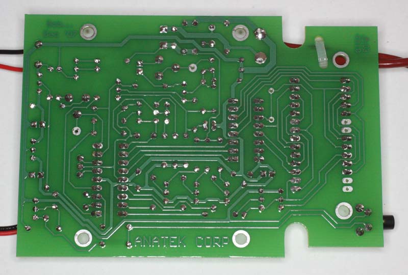 |
Fig 3 shows the solder side of the board. The assembled board has been
cleaned and given a coat of acrylic clear PCB lacquer. Quite straightforward construction.
Basic use
The instrument was assembled, calibrated and tested. It seems quite reliable
and straightforward in use. From the instruction manual:
- Insert the probe terminator of your choice into the shrouded plugs. A
croc clip works well for out of circuit
capacitors, a probe for
in-circuit.
- Press the button so the “-” symbol appears on the display.
- Hold the test probes tightly together – the test lead resistance is
displayed.
- With the probes still together, press the button again to give a zeroed
reading of “.00”. You can repeat this at
any time.
- Measure the capacitor’s ESR (it should be discharged first). A reading
of “-” indicates a reading greater than
99!. Compare the reading to the
graph on the front label. Good capacitors will have ESR below the graph
lines,
bad above.
- When you’ve finished measuring, press the button with the probes
separated. The meter switches off when
you release the button.
- When the battery is getting low, “b” flashes once per second and the
display dims to conserve the remaining
battery capacity.
Suggested improvements
All in all, a dated but good design well implemented. If anything, the wider
use of switched mode power supplies makes the instrument more relevant than in
earlier times.
Nevertheless, some things I would suggest:
- Bootlace terminals are very effective in preventing conductor strands
spreading under the screws of the supplied banana plugs.
- Provision for an external power jack for occasional users where the
internal battery is just a nuisance. I have made a small adapter from the
216 cell header to a line 2.1mm DC jack and made a small notch om the cover
to accommodate the adapter cable.
- Assembly instructions refer to parts designators (eg R10, R11 etc) but
they are not marked on the PCB overlay, rather the values are shown. My
preference is for the part designator.
- Update the instructions for the parts actually supplied.
Links
Changes
| Version |
Date |
Description |
| 1.01 |
14/04/2012 |
Initial. |
| 1.02 |
|
|
| 1.03 |
|
|
| 1.04 |
|
|
| 1.05 |
|
|
© Copyright:
Owen Duffy 1995, 2021. All rights reserved. Disclaimer.