Modem reset mod
The problem
I have experience problems with modems 'locking up' in certain
situations. The symptoms are that the modem is off
hook but no longer passing data, and does not respond to input on the
V.24 interface. It not possible to get into
command mode, and the modem does not hang up when DTR is dropped
(configured with AT&D2). It would seem that the
CPU in the modem has got into a loop and is not scanning the V.24
signals and other inputs.
It has not been possible to reset the modem other than by removing
the power. This requirement for physical
intervention is often inconvenient and expensive in lost availability,
travel and time.
The challenge is to find a way to enhance the reliability and
availability of the modem.
The following describes a watchdog that monitors the V.24 /DTR and
/OH leads (at TTL/CMOS levels) and when
conditions indicate that the modem is locked up, it pulls the modem
/RESET line low to force reset of the modem
(similar to the reset at power-up).
Disclaimer
Such a modification may invalidate modem warranty, and modem type
approvals, you may even damage the modem. The
changes are external to any analogue signal paths and only serve to
disconnect a modem that has failed in the off-hook
condition,
The modification was developed and has been successfully deployed on
five different modems and has worked as
expected.
I do not warrant the modification in any way,
you do any such mods entirely at your own risk,
even if I supply you with a chip and / or information.
Algorithm
If /DTR has been low for at least 2.5S and goes high for at least
255mS, if /OH is low, it will pull /RESET low (via
a 100 ohm resistor) for 20mS.
If you hardwire the /OH lead from the modemrst board to GND, the mod
will force hardware reset at the end of every
'call', whereas if you connect it to the /OH line, it will only
activate in the failure scenario.
Implementation
The watchdog is implemented in a Microchip 12C508A 8 bit
microcontroller (MCU).
The only components required are the 12C508A, a 0.1uF filter
capacitor for Vdd, and a 100 ohm resistor in series
with the RESET connection.
The MCU uses the internal RC clock running at 4Mhz.
Board
| This is a view of the underside of a peice of
Veroboard showing the track cuts. Note that the track is
cut between holes rather than drilling out the track around a hole. |
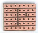
Fig 1: Veroboard track detail
|
| View of a finished board. You can see the
resistor and capacitor on the left side of the chip. The chip
is socketed in this prototype.
The whole assembly is in shrink plastic tube to protect and
insulate it.
|
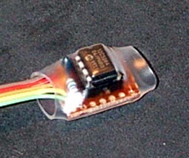
Fig 2: Finished assembly
|
Modem specifics
This section contains some details of connection points for three
modem models on which I have tested the mdmrst
chip. Whilst I have used other brands of modems, the lock up problem
that I have described has been consistently
observed on the three modem models below. I would expect that other
models and brands built on the same chip set and
software base may well exhibit the same problems.
ME071
VSS is available at the cathode of the PWR LED. VDD is available
from the end of R24 nearest to the edge of the PCB.
/RESET can be picked up from the via between C35 and the chip socket,
/DTR is available from the via near pin 22 of
U9.
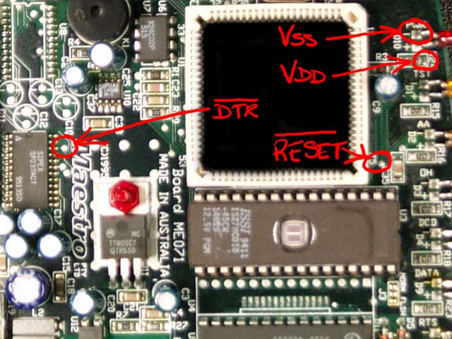
Fig 3: ME071 connection points
ME090
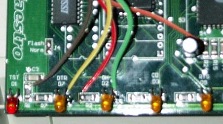
Fig 4: ME090 connection points
ME100
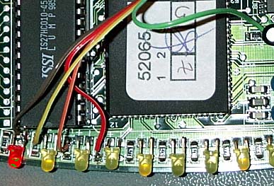
Fig 5: ME100 connection points
Conclusion
After two years of operation, the two modems fitted with this
modification have not required any manual intervention
due to lock-ups, whereas without it such intervention was necessary on average
a few times per year.
The mdmrst mod has been successful in significantly improving the
availability of the modem ports.
© Copyright:
Owen Duffy 1995, 2021. All rights reserved. Disclaimer.