 |
| OwenDuffy.net |
|
This article contains notes on installation of a Roger Beep inside an Icom SM8 microphone.
There is very little space in the microphone base, but a Roger Beep module can be accommodated, and it provides a neat solution for integration of the Roger Beep with one or two transceivers.
CAVEAT: Any modifications that you make to your transceiver are entirely your own responsibility. Owen Duffy takes no responsibility for the accuracy of this article, or for the outcome of your modifications. Modification of a transceiver may have implications for original warranty.
The SM8 base has very little spare room, but with a little care, a Roger Beep module can be fitted.
Before constructing the module, remove about 1.5mm from the top and bottom edges of the board, and about 2.5mm from the side edges. DO NOT grind any tracks or pads away.
When installing the FET, leave sufficient lead length to bend it inwards at 45° to the board.
| Roger Beep Pin | Description | Connection details |
| 1 | +DC | Connect to the cathode of the diode near the socket for mic 1 |
| 2 | Reset (NC) | Not used |
| 3 | PTT in | Cut the lead of the RF choke near the
locking PTT switch, so that wires can be attached to
the lead coming out of the PCB and the free end of the RF choke, and
push the RF choke sideways a little to make space
.
Connect to the lead coming out of the PCB. |
| 4 | PTT out | Connect to the free end of the RF choke. |
| 5 | Ground | Connect to the same pad as the shield from the electret insert. |
| 6 | Audio out | Connect to the same pad as the inner conductor from the electret insert. |
Construct the module, and connect the wires as in Table 1. The work can be done without removing the SM8 PCB.
|
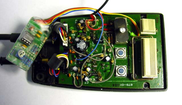
Fig 2 shows the module installed in an SM8. The Roger Beep board was trimmed down a little to remove PCB material without grinding away an tracks. The module is encapsulated in heatshrink tube. Note the hole cut in the shrink wrap to provide access to the level adjustment pot.
Test and adjust the Roger Beep before closing the case.
The module is located behind the PCB, angled with the lower edge forward and bearing on the mic cables, and the upper edge backwards. Make sure that the ferrite beads on the mic cables are lifted upwards so that the module can slip in underneath them. Carefully close the cover over the base, jiggling the module and cables to fit. As the case finally closes, the module will push down on the mic cables, holding the module in place without rattles. Check that all the switches operate freely and that the case closes without pinching any wires.
Before finally tucking the module into the transceiver:
| Version | Date | Description |
| 1.01 | 05/06/2009 | Initial. |
| 1.02 | ||
| 1.03 | ||
| 1.04 |
© Copyright: Owen Duffy 1995, 2021. All rights reserved. Disclaimer.