| OwenDuffy.net |
|
This article is a report on an attempt to test a Turnigy 2211-2300 brushless DC motor.
The motor on first inspection is very nicely made, and appears stunning value if it works to specification.
The motor was secured in a test fixture by the supplied mount feet without undoing any motor fasteners.
|
|
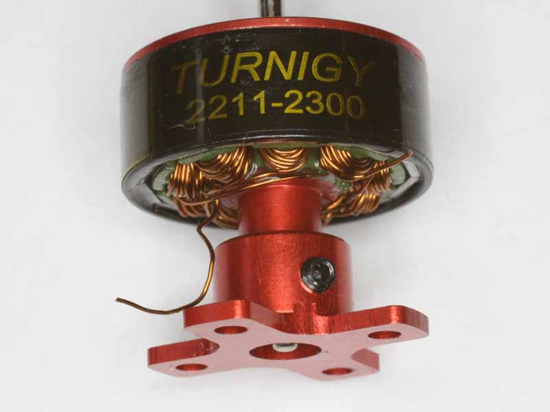
Fig 1 shows the mount arrangement for the motor, a pair of grub screws clamps the mount to the motor support tube. This is a very common configuration for outrunners.
During a test attempt, the motor flew from the mounting at about half rated input power with a propeller load (5030 three blade). The spinning motor then twisted the wires from the ESC together, shorting the ESC and destroying it, and hitting me in the forehead some 700mm from the test fixture.
|
|
Fig 1 shows the scrape marks made by the grub screws as the motor support tube escaped the mount. Since this was at relatively low power, the motor as it left the factory was not suitable for the intended purpose and indeed unsafe. The pressure from the both grub screws has been sufficient to carve a track in the motor support tube as it flew out of the mount... but not sufficient to hold it safely in the mount, and this occurred at about half rated input power (thrust < 2N).
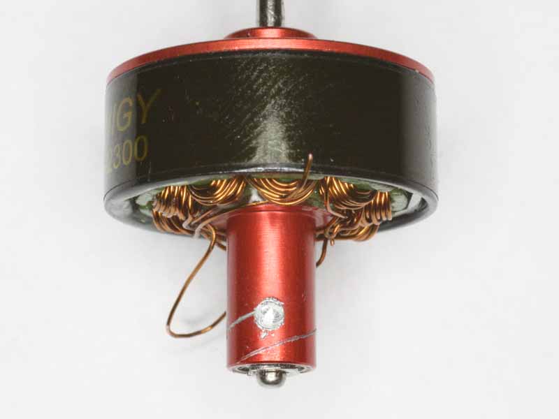 |
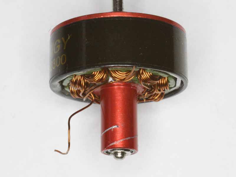
Fig 3 shows a modification to the motor support tube to help to prevent escape of the motor from the mount. A small depression large enough to accommodate the grub screw end was cut into the motor support tube using a round engraving point. The grub screw locates in this depression, and if the motor is wiggled during assembly, the grub screw point will locate in the centre of the depression. The other grub screw is then tightened. The use of thread locking compound if possible will assist integrity. This modified support tube arrangement resisted 200N static force, more than 60 times rated thrust (<3N).
It was found that without the depression, even with both grub screws very tight, the mount slipped at 50N. Although this is well above the normal operating load, it is felt that it worthwhile to modify the support tube as described and to use thread locking compound on the grub screws.
A disadvantage of this motor configuration is that the mount screws are not very accessible with the mount secured to the motor support tube. It might just be a configuration that is best avoided.
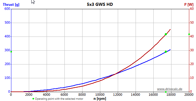 |
Fig 4 shows the characteristics of the propeller load used, and the basis for thrust estimates. The propeller is fairly well matched to the motor characteristics on 3S battery. The graph from Drive Calculator is scaled in grams force, but the correct ISO unit for force is Newtons (N), and grams force must be multiplied by 9.8m/s^2 to get force in N, so 300g force is just under 3N.
The grub screws have nominal 1.3mm socket grub screws. A tool of 1.28mm could not be inserted in either of the three grub screws, but a smaller key of 1.23mm worked. The ISO tolerance of sockets is usually positive (eg Unbrako specifies tolerance class K9 which is +25*0.001 which is 0 to 0.025mm oversize), they should never be less than the nominal size but these grub screw sockets were between 1.23mm and 1.28mm.
| Version | Date | Description |
| 1.01 | 30/05/2013 | Initial. |
| 1.02 | ||
| 1.03 | ||
| 1.04 | ||
| 1.05 |