| OwenDuffy.net |
|
This article is a collection of build notes for my Q450 quadcopter project.
The project design is derived from two existing quadopters, X450 quadcopter - Q11 (19/03/2015 build) and Q450 quadcopter - Q21 (30/06/2016 build). Essentially it is motors and propellers from the first, and almost everything else from the second.
Key elements of the configuration are:
The mass of the fully populated quad is ~1300g.
The size is 460mm diagonal between motor shafts and it can swing props up to about 11", though gear in the middle may limit propellers to something less. This project uses 11" propellers.
|
|
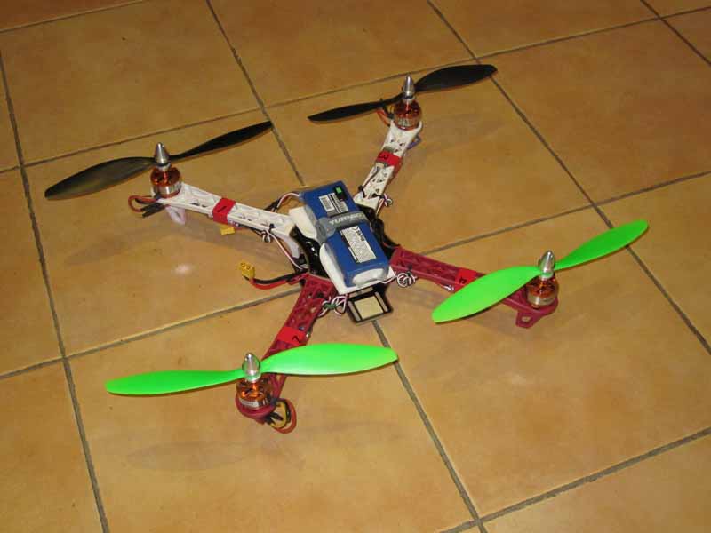
Fig 1 shows the built quadcopter.
|
|
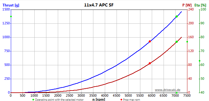
Fig 2 shows the characteristics for a similar 1147 SF propeller. The green dots are for an operating point of 1377g thrust for each propeller at 10.0V (WOT on a flat battery), and the indicated motor power is 147W at is 7060RPM.
At 8.3V, the motor should achieve about 6,310RPM and about 375g of thrust which would accommodate a payload of perhaps 750g with reduced performance. Under these conditions, motor output power would be about 40W each, DC current about 6A each or 24A in total (10C) and motor dissipation around 20W each. Overall, operation at that power is well within the limit of the battery current, mission time is dramatically reduced.
|
|
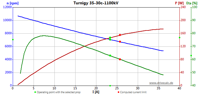
Fig 3 shows the loaded motor characteristics. The green dots are for an operating point of 1377g thrust for each propeller at 10.0V (WOT on a flat battery), and the indicated motor power is 234W at is 7060RPM. The efficiency scale (eta or η) may be optimistic as the model does not properly take into account the efficiency impact of PWM operation where shorter pulses of higher current create more winding loss than the DC equivalent current.
The following are notes on the construction. Some issues were noted during initial build, some a little later.
|
|
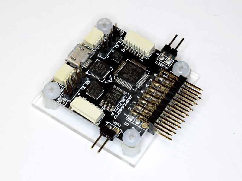
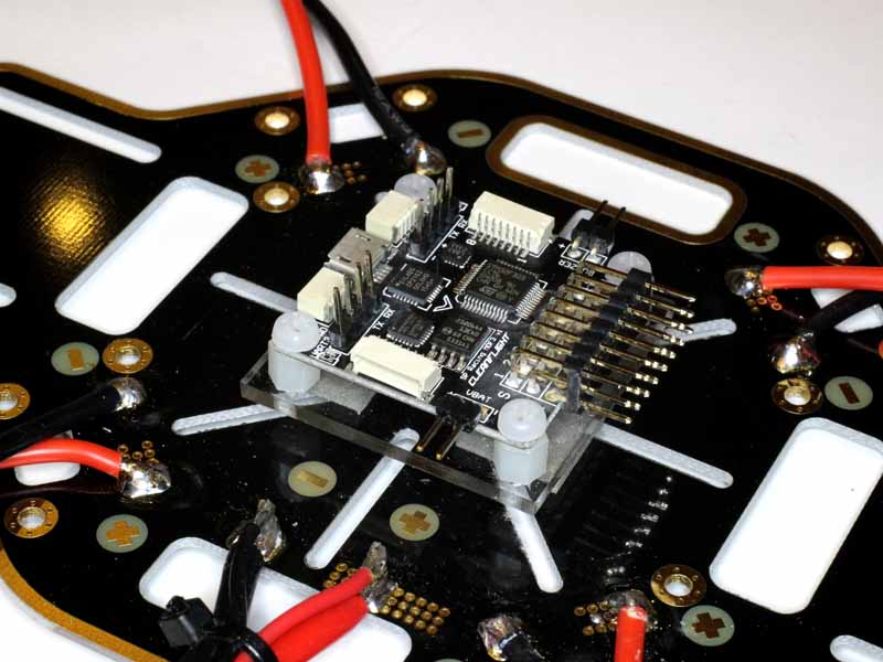
Fig 4 shows the FC.
|
|
Fig 4a shows the FC which is mounted to a small square of acrylic which is to be foam mounted to the frame. A 15mm square of medium density open cell foam was placed between the barometer and acrylic base to improve ALT HOLD stability.
|
|
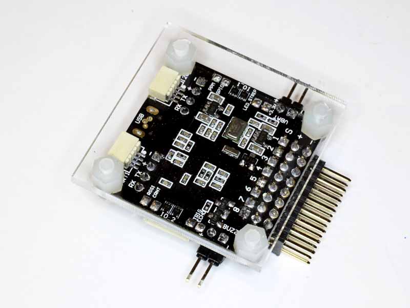
Fig 4b shows the FC in the frame mounted on two double sided adhesive foam pads for vibration isolation.
The quad uses nominally 11"x4.7" two bladed slow fly propellers. These are available from a range of sources, and initially the cheap ABS plastic ones have been used.
The motors included propeller mounts with collets to suit the 5mm plain shafts, and M8 threaded extension for the propeller.
Power distribution uses the frame's integral distribution board. The ESCs are soldered to the distribution board.
Features include:
Variations:
| Channel | Use | FC pin | Tx | Comment |
| IO_1 | PPSUM | 3 |
Table 1 shows the receiver connections.
| FC pin | Motor | Comment |
| M1 | Right rear | |
| M2 | Right front | |
| M3 | Left rear | |
| M4 | Left front |
Table 2 shows the ESC connections.
| Bluetooth pin | FC pin | Comment |
| Vcc | +5 | |
| Gnd | Gnd | |
| Rx | Tx | |
| Tx | Rx |
Table 3 shows the Bluetooth connections. Connection protocol is 115,200,8,n,1.
 |
Fig 5 shows the configuration tool sensor screen with the quad hovering but loosely held in the hand. The purpose of this test was to evaluate the residual vibration sensed by the board.
|
|
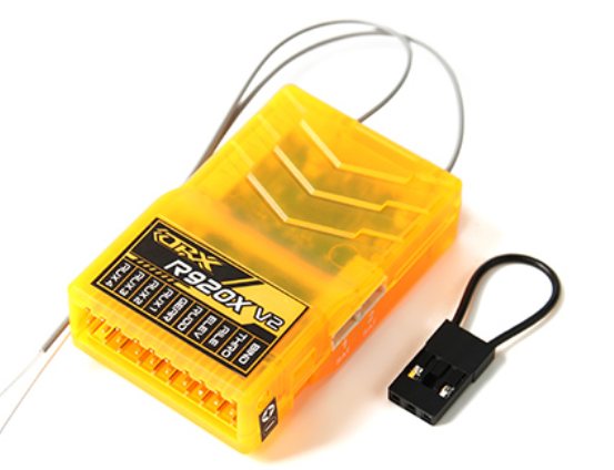
Figs 6 shows the Orange R920X receiver.
An inexpensive HC05 Bluetooth module was connected for field tuning purposes using a smartphone app. The module was configured for name Q21, 115,200bps, 8n1.
The F-30A ESCs were upgraded to tgy (SimonK) bootloader + tgy bs_nfet.hex firmware.
Current version: 1e4c01782eff85da3971f628a3bd599b7a0725eb bs_nfet_mw.hex 18/10/15
For this application:
.equ MOTOR_ADVANCE = 15 ; Degrees of timing advance (0 - 30, 30 meaning no delay) .equ TIMING_OFFSET = 0 ; Timing offset in microseconds (max 4096µs) |
The motors are Turnigy Turnigy D3530-14 1100kv Brushless Motor, specifications:
Battery: 2~4 Cell /7.4~14.8V
RPM: 1100kv
Max current: 22A
No load current: 1.6A
Max power: 315W
Internal resistance: 0.077 ohm
Weight: 73g (including connectors)
Diameter of shaft: 5mm
Dimensions: 35x30m
Prop size: 7.4V/12x6 14.8V/8x4
Max thrust: 1100g
Poles: 14
Turnigy 5000mAh 10C.
The FC has integral battery monitoring.
A static thrust test was conducted at 10V (low limit for a 3S battery). Experience is that a quadcopter needs 2g excess thrust to safely and quickly land at the low battery limit. Since the craft mass is 1300g, its gravitational force is ~13N, and 300% thrust is 39N, 9.8 per motor. Static thrust was measured at 21.1N on 10V @ 24.1A (per motor), 7100RPM. Total current of 100A from a 4Ah battery requires at least a 25C battery.
Hover will require about 3N and that can be achieved on 10V @ 4A (per motor), 4000PM. At a total hover current of 16A (worst case), endurance on a 5Ah battery should be about 18min.
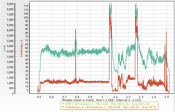 |
Fig 7 shows a test of the quad at 12.6V. There was 0.7A current drawn by the four ESCs and FC with the motor OFF, so 0.7A needs to be deducted from the figures in the graph.
Hovering rpm is around 4,000, avg motor current consumption was 16-0.7=15.3A.
A series of full stick accelerations was conducted, and current peaked at 110A, rpm peaked at 8,300.
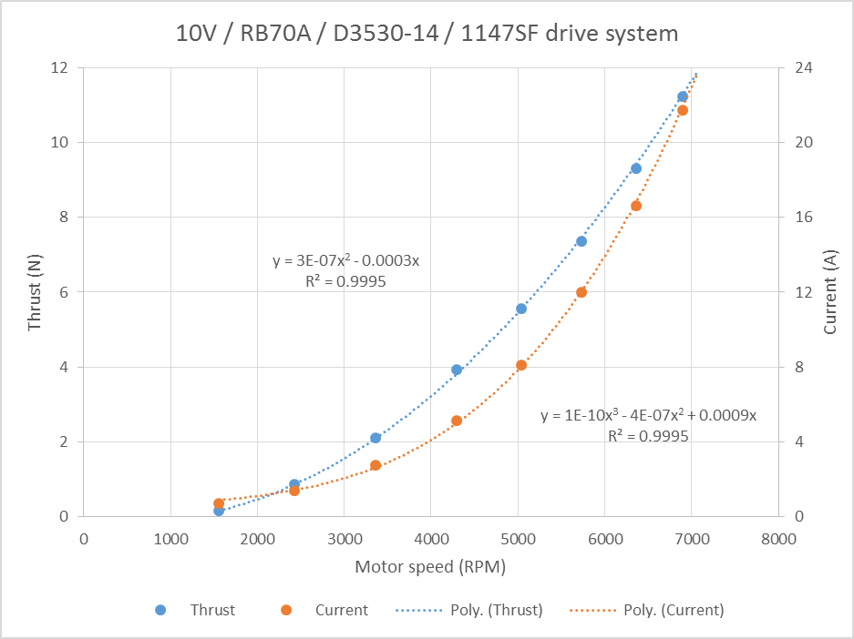 |
Fig 8 shows static measurement of current and thrust and current of a single motor at 10.0V (motor tested with RB70A as it was on hand).
The graph indicates hover thrust (3.3N) is delivered at 4000rpm with 4.2A per motor giving an endurance of 14min on a 4Ah battery (at 10V).
These measurements reconcile quite well with the DC3.4 prediction presented earlier.
Crash damage has mostly been to the propellers which seem reasonably robust... but they are breakable.
A couple of spare frames were purchased to provide spares.
| Version | Date | Description |
| 1.01 | 30/06/2016 | Initial. |
| 1.02 | ||
| 1.03 | ||
| 1.04 | ||
| 1.05 |
© Copyright: Owen Duffy 1995, 2021. All rights reserved. Disclaimer.