 |
| OwenDuffy.net |
|
A bootloader is a program that loads the 'main' program. In this case, it is a set of instructions that are loaded into the top of the microcontroller's memory, and it provides for loading a program into the lower part of memory, and data into EEPROM.
The AVR ATTiny series microcontrollers use flash memory for the program memory, and in a modification to the Harvard architecture, the program memory can be read and read and written by the program.
ATTiny microcontrollers do hot have hardware support for a boot section of flash memory, meaning lacking hardware protection of the boot section from corruption. They also lack some facilities which one might require for distributing copy protected updates.
Small flash size means memory is at a premium.
The ATTiny processors do not universally have a USART, so serial communications is done by bit banging. Flexibility is enhanced if the bootloader can adapt to host speed reliably, and so an autobaud function was implemented.
The decision to implement CRC was in some ways a hard one as it costs about 25 words of flash, about 10 for the CRC calculation routine, and the balance for calling the routine character by character, and handling the outcome. The data transfer proved very reliable, but this might be less so for some crystal frequencies that stretch tolerance of speed error to the limit, and so the decision became an easy one, CRC improves confidence in marginal cases... and end users don't want to be diagnosing problems with boot loaders. The CRC protects blocks of data to be written to flash or EEPROM, so the risk of writing corrupt data to either area is very low. (The experience of using ATB for literally hundreds of flash and EEPROM writes followed by a verify is that there have been zero CRC errors, zero verify failures. The system is so reliable that end users would bypass the verify test, more reason to do the CRC check.)
The result so far: the code requires almost 300 program words, or about 7.5% of a 8k flash part such as an ATTiny85.
The design philosophy has been to strive for reliability and performance in that order. There are no bells and whistles, it is pruned down to minimise size, but is reliable and fast.
Many existing bootloaders were examined for inspiration, see the reference list at the bottom of this article. They each have interesting features and contain the results of some serious thinging on the problem, a credit to all developers.
Notably, this design does not use an existing protocol (such as STK500), rather it uses a very simple protocol designed to minimise memory requirements. The protocol is not compatible with any bootloaders I have surveyed. For that reason, it requires its own host client program.
The design does not attempt to deliver:
This bootloader communicates with the outside world over a single wire or two wire half duplex asynchronous TTL interface. When an External Reset occurs (grounding the /RST pin), It listens on the receive pin for specific serial data and attempts to measure its speed so as to synchronise its bit clock with the sender. If it does not receive the expected data, it times out and passes control to the program resident in the lower part of flash memory. If the receive pin is low on reset, the bootloader is bypassed immediately.
When communication is established with the host computer, typically using a RS232 (COM or tty) port, or USB adapter simulating an RS232 port and some sort of level conversion to TTL levels used by the microcontroller pin, the bootloader responds to commands from the external host.
The commands support writing, reading, verifying and erasing application flash (ie the part of flash not used by the bootloader) and EEPROM memory.
In this implementation, blocks of data to be written to flash or EEPROM are protected by a CRC-16 checksum over the communications link. If an error is detected, the process will abort and the user can retry. Errors should be very rare and the low incidence does not warrant committing memory to automated retry. If writing to flash aborts, the bootloader erases all application flash to protect against the risk of unpredictable or even adverse behaviour of a part loaded program which might frustrate access to the bootloader, or damage the bootloader. (In this series of AVR chips, the chip does not have hardware to protect the bootloader being overwritten by the application program.)
If data transmission errors are encountered, it is probably that speed is too high for the microcontroller clock speed. Try a lower transfer speed.
ATB contains no features to copy protect the programs or EEPROM data to be loaded using ATBU. The user of ATBU must have a clear text copy of the programs and EEPROM data to be loaded. Anyone with ATBU can read the contents of the program and EEPROM memory that has the ATBF bootloader installed, even if the AVR fuses limit access to the memory.
The autobaud scheme is a simple one, similar to that described in Microchip's AN712. The implementation has been tested extensively on an ATTiny44 using the internal RC clock with and without CKDIV8 fuse, so 8MHz and 1MHz clock. At 8MHz, the system has worked reliably with two USB/RS232 adapters at 1200-230,400bps.
Lower speed clock means lower maximum bit rate, and some clock rates will permit higher speeds because of their close harmonic relationship to the bit rate.
Speed distortion is lowest when there are many clock pulses per data bit, though for some clock rates that are closely harmonically related to the data rate, acceptable speed distortion may still be obtained.
The bootloader uses half duplex communications, so can use a single wire interface. Sufficient delay has been introduced in operations to allow for turning the line around.
In the two wire interface, transmit uses one microntroller pin and receive uses another pin. The transmit pin is operated with active pull-up / active pull-down and offers the best signal quality, especially at high speed.
The transmit and receive pins do not need to be dedicated to the bootloader, they can be shared providing appropriate methods are used to isolate other use of the pins during bootloading. Of course, if the microcontroller already has a RS232 interface or equivalent, that interface can be shared by the bootloader.
A single wire interface potentially has senders at each end of the link. Damage may occur if one of those senders asserts a logical 1 using active pull-up when the other asserts a logical 0 (which is always an active pull-down).
The safe way to avoid this conflict is to use open collector style of operation of the two sending interfaces.
|
|
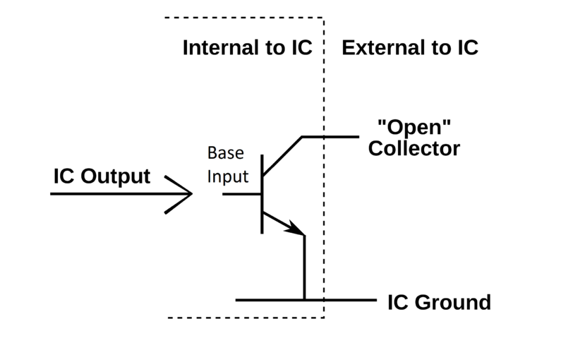
Fig 1 above from (WIkipedia 2012) shows the open collector style of output. A logic 1 is obtained using an external pull-up resistor. An equivalent can be done with FETs to produce an open drain output. The key thing is that a bus using this style of output drivers can have many outputs without the risk of excessive current and unpredictable operation if a bus has both active pull-ups active and another output pulling down.
In the case of the bootloader firmware, two versions are available, one uses open collector style output where the output pin is either configured for logical 1 as an input with internal weak pull-up resistor, or for logical 0 as an output asserting low. Though the weak pull-up is configured, it is not sufficient for reliable operation of the interface, especially at any speed, and an external pull-up resistor is required.
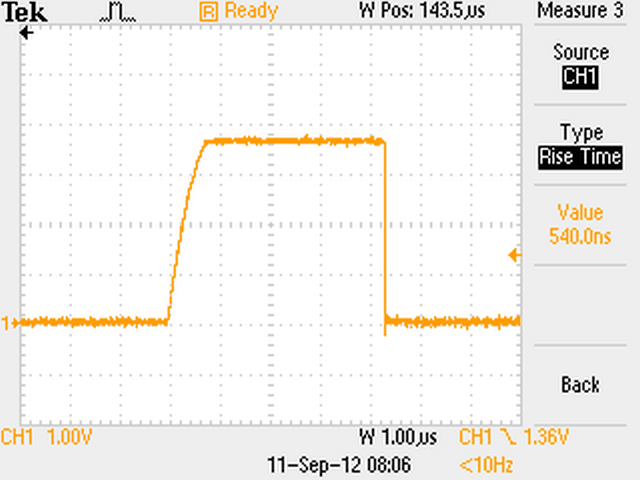 |
Fig 2 above shows the 230,400 bps single wire data waveform in the prototype using a 10kΩ pull-up resistor. The programming adapter is PL2303 based and has about 700mm of cable to the prototype. Waveform risetime is better with a shorter cable, or lower pull-up resistor, <30ns was obtained with an FTDI adapter with 150mm of serial cable and 10kΩ pull-up resistor.
Two wire operation with active pull-up would deliver better pulse rise time than the single wire adapter.
The AVR chip pins use TTL voltage levels, and a real RS232 port uses different signal voltages. An adapter is required to interface the two.
There are a plethora of adapters that extend a physical or virtual COM port to TTL levels.
Recent adapters purchased have not worked and appear to have counterfeit chips in them, see Prolific PL-2303 problems for more information.
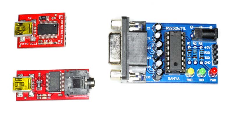 |
Fig 3 shows a collection of adapters. The two on the left are USB/RS-232(TTL) adapters using an FTDI chip. The one at the top left is from Sparkfun and is available with 3.3V or 5V T/R output. Note that the one on the lower left is an adapter for Picaxe which emulates the Picaxe cheap and nasty interface with bodgy pinout (the sleeve of the TRS jack is NOT grounded) and it is inverted (which can be changed by reprogramming the FTDI chip). None of these are open collector outputs, if single wire operation is desired an isolating diode is needed to synthesis an open collector.
The adapter on the right in Fig 2 is a RS-232(TTL) adapter using a MAX232 chip. This is not an open collector output.
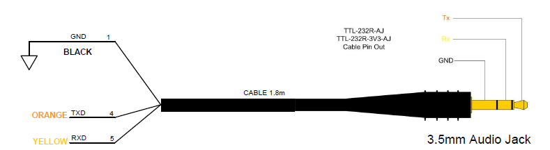 |
Fig 4 shows the pinout of the FTDI USB/AudioJack adapters. This convention is commonly used, but some PL2303 based adapters on the market use Tip for Rx, Ring for Tx and Sleeve for Ground.
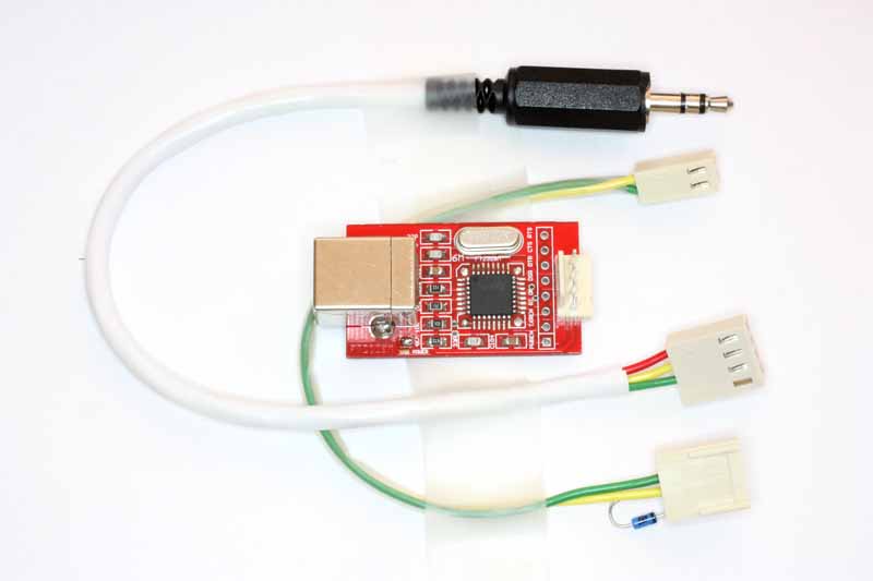 |
Fig 5 shows an inexpensive ($12) FTDI based adapter which has had a polarised 4 pin header installed, and two cables, The 3.5mm TRS plug is a two wire interface, and the 2 pin header cable is a single wire interface (the diode to combine Tx and Rx can be seen on the 4 pin header plug). The advantage of this configuration is short cables on the high speed RS-232(TTL) side. This set has been used extensively during devlopment and testing of ATB.
Of recent times, there are a growing number of FTDI based cables with either a 6 pin header for Arduino use, or 6 individual single header pins which are eminently suited to this application. These are often available for below A$10 including post.
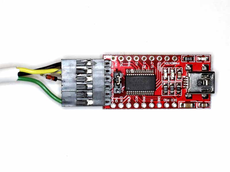 |
Fig 5a shows a variant of the Arduino style FTDI adapter. The cable colours are green: ground; yellow: tx/rx half duplex; black DTR for Arduino style reset (10k pullup resistor on /RESET, 0.1µF cap from DTR to /RESET, see below). The 3.5mm wiring is T:DTR; R: tx/rx; S: ground.
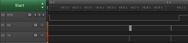 |
Fig 5b shows the timing of start of communications using DTR reset, the first probe from the host is sent about 650ms after the DTR transition so the target must be up and running in that time, and it must remain in boot mode until that time.
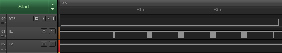 |
Fig 5c shows an entire read EEPROM transaction.
Adapters from either RS232 or USB to Icom's CI-V bus and their programming adapters should work, they are a single wire half duplex arrangement and those with a 3.5mm TRS plug are most suitable, the Tx/Rx is on the Tip or Ring (depending on the adapter type), Ground on the Sleeve of a 3.5mm TRS plug. They should be open collector output, but lots of hobbyists in ignorance design adapters that are not open collector... check the circuit carefully. Two adapters of this type have been tested to work properly on the prototype. Clones sell for about $10 on eBay.
See Prolific PL-2303 problems for more information.
Yaseu programming adapters tend to be two wire TTL adapters and may be suitable, but most have connectors that are not wonderful choices for ATB applications.
See Prolific PL-2303 problems for more information.
An open collector output can be synthesised for active pull-up outputs by inserting a diode in series with the output pin, cathode to the output pin. So for the single wire bus, connect the bus directly to the adapter's Rx pin, and via a diode to the adapter's output pin, cathode to the output pin. The diode should have a low forward voltage drop, eg a germanium (1N34A) or schottky diode (1N5711). A 1N5711 was used for prototype testing.
If a /DTR signal is available from the serial interface, a 0.1µF capacitor can be connected from that pin to the /RST pin of the AVR chip, and a 10kΩ pull-up resistor on /RST. If that is done, when ATBU opens the serial port to communicate with ATBF, the transition on /DTR will reset the AVR. ATBU has a 200ms delay to allow for the chip to reset before sending data to it. This scheme is used widely on later Arduino boards (ASR feature). ATBU also asserts RTS in the same way, and it can be used in place of DTR if the adapter has RTS available but not DTR.
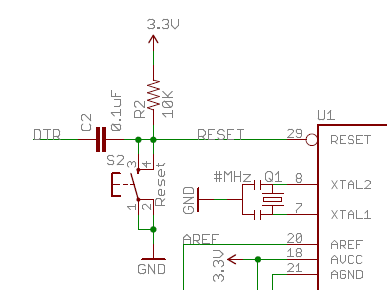 |
Fig 6 shows the relevant part of the Arduino PRO schematic. (The DTR lead is actually /DTR and RESET is /RST.)
Firstly, a flash image of ATBF customised for your Tx/Rx pins and timeout must be generated using ATBU.
C:\src\PllLdr\ATB>atbu.exe -s 18000 -oG:tn44 -r a1 -t a1 -f tn44.hex Utility for Avr Tiny Bootloader (ATB), v1.05. Make ATBF from code template tn44 using PA1/PA1 for RX/TX. 100% ################################################## Generate done. Saved ATBF file: tn44.hex |
Fig 7 shows generation of an ATBF image for an ATTiny44 using PA1 for Tx and Rx (single wire), and timeout factor set to 18000 (about 4s at 8MHz).
ATBF must be loaded onto the AVR chip using a conventional programmer.
To use ATBF, you MUST program the SELFPRG fuse on the ATTiny microcontroller (allowing programs to write to flash). If you program the fuses to prevent conventional programmer access to flash or EEPROM, you can still read and write them using the bootloader.
C:\src\PllLdr\ATB>avrdude -P usb -c avrisp2 -p t44 -U flash:w:tn44.hex avrdude: AVR device initialized and ready to accept instructions Reading | ################################################## | 100% 0.02s avrdude: Device signature = 0x1e9207 avrdude: NOTE: FLASH memory has been specified, an erase cycle will be performed To disable this feature, specify the -D option. avrdude: erasing chip avrdude: reading input file "tn44.hex" avrdude: input file tn44.hex auto detected as Intel Hex avrdude: writing flash (4034 bytes): Writing | ################################################## | 100% 0.49s avrdude: 4034 bytes of flash written avrdude: verifying flash memory against tn44.hex: avrdude: load data flash data from input file tn44.hex: avrdude: input file tn44.hex auto detected as Intel Hex avrdude: input file tn44.hex contains 4034 bytes avrdude: reading on-chip flash data: Reading | ################################################## | 100% 1.25s avrdude: verifying ... avrdude: 4034 bytes of flash verified avrdude: safemode: Fuses OK avrdude done. Thank you. |
Fig 8 shows loading the bootloader (tn44.hex) using AVRDUDE.
ATBU is the host end client program for working with the ATBF bootloader firmware.
C:\src\PllLdr\ATB>atbu -ccom14:230400 -oI Utility for Avr Tiny Bootloader (ATB), v1.05. Half duplex activated. Communication established, boot loader engaged. AVR TINY BOOTLOADER (ATB) Version : 1.1.0 Signature : 1E 92 07 PAGESIZE : 64 FLASHSIZE : 3392 EEPROM : 256 TIMEOUT : 18000 |
Fig 9 shows an enquiry to check device communication and get the key device characteristics. Though the timeout value was explicitly set in Fig 7, if it is not set, the default value gives 2s timeout with a 20MHz clock.
C:\src\PllLdr\ATB>atbu -oEW -f 1.hex -ccom14:115200 Utility for Avr Tiny Bootloader (ATB), v1.05. Half duplex activated. Communication established, boot loader engaged. 100% ################################################## Write done. |
Fig 10 shows the command execution to load the EEPROM from a hex file. The EEPROM and flash are loaded independently, and either can be replaced at will. In this case, the parameters for the flash program are held in EEPROM, and they can be updated at will using ATBU.
The microcontroller MUST be reset after each ATBU operation, for safety the microcontroller freezes at the end of command execution.
C:\src\PllLdr\ATB>atbu -oFW -f pllldr.hex -ccom14:115200 Utility for Avr Tiny Bootloader (ATB), v1.05. Half duplex activated. Communication established, boot loader engaged. 100% ################################################## Write done. |
Fig 11 shows the command execution to load the flash from a hex file.
An update at 11/11/12: ATB has been used extensively in house and EVERY failure to perform has been investigated. To date, I am pleased to say that after more than a thousand ATBU commands spanning several projects, no failure has been attributed to ATB firmware or utility program. The failures, and they are rare, have been hardware problems (eg incorrect wiring, unpowered targets, etc), and simple operator errors (command line errors etc)... the things we do when we are tired! Importantly, a resident bootloader has NEVER been damaged by the use of ATBU.
| Version | Date | Description |
| 1.01 | 11/09/2012 | Initial. |
| 1.02 | ||
| 1.03 | ||
| 1.04 | ||
| 1.05 |
© Copyright: Owen Duffy 1995, 2021. All rights reserved. Disclaimer.