 |
| OwenDuffy.net |
|
As part of its web site marketing, PowAbeam Antennas publishes an apparently nifty little calculator that would seem intended to inform of the impact of mismatch on loss.
Lets explore it with examples that will expose the pitfalls in using and interpreting such a calculator.
(Note, that since first publication of this article, PowAbeam's calculator has been changed to address some of the issues mentioned in this article, but the matter of the relevance of Mismatch Loss stands.)
The example scenario is:
Note that this is a fairly low loss line, and VSWR will be approximately 10:1 over the whole line.
A practical dipole of this size will typically have very low losses, and for the purposes of this analysis it is taken as relatively insignificant.
| Content removed... |
Filling in the LETS GET REAL ABOUT VSWR calculator (PowAbeam 2011) with VSWR=10 and clicking SUBMIT, we get the results in Fig 1.
Wow, this system is REALLY bad, it has 4.8dB of ACTUAL LOSS
!!!
Lets work through it and make a rational interpretation.
Firstly, the calculated Return Loss is incorrect. Return Loss is defined as the ratio of ForwardPower to ReflectedPower and expressed in dB, will ALWAYS be a positive number in passive networks (such as this). Return Loss is actually +1.7dB.
Next, Reflection Coefficient and S11 are complex quantities, they have magnitude and phase. The quantity displayed is but the magnitude of the (Voltage) Reflection Coefficient, |Γ| or ρ in a common symbology.
Next, the quantity % Reflected
is the square of the magnitude of the Voltage
Reflection Coefficient and sometimes known as the Power Reflection Coefficient, and the ACTUAL LOSS
quantity is calculated as
−10*log(1−|VoltageReflectionCoefficient|^2) which implies
−10*log(1−ReflectedPower/ForwardPower), as if Reflected Power is necessarily lost
as heat (though it doesn't state that explicitly). This quantity is usually
known as Mismatch Loss (rather than ACTUAL LOSS
), and Mismatch Loss is the reduction in load power compared to the
case of a matched load (meaning that the load is matched to the source impedance
at the reference plane).
Two key points about Mismatch Loss:
So, how much energy is lost as heat?
Lets use TWLLC to solve the transmission line problem.
| Parameters | |
| Conductivity | 5.800e+7 S/m |
| Rel permeability | 1.000 |
| Diameter | 0.0020 m |
| Spacing | 0.1500 m |
| Rel permittivity | 1.050 |
| Loss tangent | 1.000e-5 |
| Frequency | 7.000 MHz |
| Length | 0.500 λ |
| Zin | 60.00+j0.00 Ω |
| Yin | 0.016667+j0.000000 S |
| Results | |
| Zo | 586.78-j0.74 Ω |
| Velocity Factor | 0.976 |
| Length | 180.00 °, 0.500 λ, 20.898 m |
| Line Loss (matched) | 3.46e-2 dB |
| Line Loss | 0.174 dB |
| Efficiency | 96.07 % |
| Zload | 57.69+j0.00 Ω |
| Yload | 0.017334-j0.000000 S |
Table 1 above are the results from TWLLC . In this case I have modelled the case where the impedance looking into the half wave of line is exactly 60+j0Ω, and it can be seen that implies that the feed point load is actually 57.69+j0.00Ω, and that VSWR is approximately 10:1.
The ONLY way to calculate the line loss under mismatched conditions is the above, and the line loss is 0.174dB or less than 4%, 96% of the power delivered by the transmitter into its 60+j0Ω (100W as defined above), is delivered to the antenna and the feed line dissipates just 4W of power.
Now in practice, you might use an ATU to transform the 60+j0Ω load to the transmitter's preferred load impedance of 50+j0Ω, and that necessarily involves some loss, but in this scenario that is likely to be no more than a quarter of a dB, so loss from transmitter to feed point is some 0.4dB, nothing like the 4.8dB from PowAbeam's calculator.
Whilst PowAbeam's calculator might lead many to think this is a pretty shabby antenna system, but a sound analysis reveals that this is actually a very efficient antenna system.
It is not that their calculation is incorrect (though the nomenclature is wrong as noted), but it is in whether the model is valid for a given scenario, and then the proper interpretation of the results.
Note that there is a popular ham belief that reflected power travels back to the transmitter and is dissipated in the output stage. It is not soundly based, for an explanation see Does SWR damage HF ham transmitters.
So, when you see a statement like Think on this, a VSWR of
1.5:1 equates to a Return Loss of -13.98dB OR an actual loss of only 0.177dB!!
,
do think carefully of what the author means by actual loss
and whether it
is a valid statement (apart from the obvious error that Return Loss is
negative).
The example scenario is a pair of high performance 144MHz long Yagis each with 200+j0Ω balanced feed. The Yagis will be each fed by a length of 1.25λ of open wire line designed to have Zo such that the 200+j0Ω is transformed to 400+j0Ω. The two 400+j0Ω branches are paralleled for 200+j0Ω balanced combination. This analysis is of the transmission loss (ie Pout/Pin) from the combined input to the Yagi feed points.
The branches are each open two wire feedlines made of 12mm diameter aluminium tube spaced 68mm centre to centre, εr taken to be 1.05. Zo is calculated using TWLLC to be 283 ohms. The loss in each branch when terminated with a 200+j0Ω load is 0.0028dB, so the loss from the combined 200Ω input feedpoint to the Yagi feed points is 0.0028dB. The branches are mismatched, the VSWR on each branch is 1.42 (200Ω load on a 283Ω line).
PowAbeam's calculator calculates 0.133dB of ACTUAL LOSS
for the case of VSWR=1.42, but this feed system has a transmission loss
(Pout/Pin) of 0.0028dB, 99.93% of the power delivered to the input of the
splitter is delivered to the Yagi feed points. This feed system has much lower
loss than an equivalent system using practical coaxial cable, but the same
calculations could be done for a coaxial feed, the same theory, the same
mathematics apply.
It is a mistake to think that that Mismatch Loss (or ACTUAL LOSS
in PowAbeam's nomenclature) has any relevance in this application.
The following are examples of misleading definitions of Return Loss. Some are antenna manufacturers, some are consultancies, all are commercial entities promoting their wares.
(M2 Antenna Systems Inc 2008) VSWR - Voltage Standing Wave Ratio is the logrithmic
description of the power the antenna accepts versus the amount it
reflects back down the feedline. Synonomous with Return Loss
[sic].
(RFCables.org 2011)
|
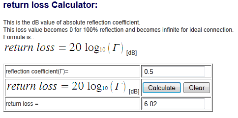
Fig 2 shows a formula that calculates negative Return Loss, yet the calculator in this case has correctly calculated a positive value. The Formula should read ReturnLoss=-20log(|Γ|).
(Telestrian Limited 2011)
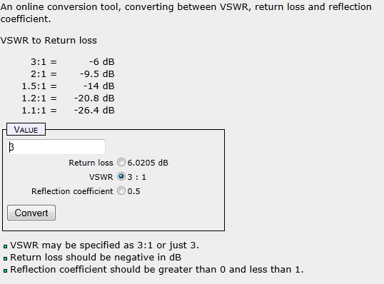 |
Fig 3 shows a table of incorrect negative values for Return Loss, the calculator correctly calculates a positive value, and the definition at the bottom is wrong in insisting that Return Loss is negative.
(Antenna Designer UK 2010)
| Content removed... |
Another instance of the same calculator as (PowAbeam Antennas 2011).
(Directive Systems 2010a) is an article discussing Return Loss and has several graphs labeled return loss showing negative quantities. The graphs are actually S11 plots from a VNA, and the author apparently doesn't know the difference between the meaning of Return Loss and S11.
At (Directive Systems 2010b) they have their definition of Return Loss:
Return loss is a measure the the power level obtained from an rf bridge network when compared to the output of the same bridge terminated in a short circuit or an open circuit. Simply put, the bridge is balanced and has no output when terminated in a 50 ohm load (1:1 VSWR) and has maximum output (infinite VSWR) when the bridge is terminated with a short or open circuit. The return loss value is the value of attenuation of the reflection signal.. For example, a 1.5:1 VSWR is the equivalent of a 14 dB return loss value. In this case the rf bridge output is 14 dB less power than if it were directly shorted or open at the "test" port.
A lot of words, not very clear, but a measure the the power level obtained
from an rf bridge network when compared to the output of the same bridge
terminated in a short circuit or an open circuit
gives a negative quantity,
yet the example is a positive quantity, and the lookup table is correctly
positive. The article is internally inconsistent.
(McCarthur 2009)
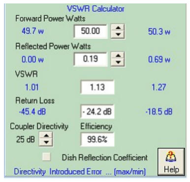 |
In the VSWR caclulator sub element above, the sign of Return Loss is incorrectly shown as negative..
The promotional article (Array Solutions 2013) gives VSWR and Return Loss plots with Return Loss on a negative scale.
Example image not shown here because Array Solutions attempts to stifle comment and critique of their web content and whilst under copyright law they cannot prevent discussion and critique, they may be able to restrict copying of images.
Beware of buying products from a seller who is not comfortable with open discussion of their product!
© Copyright: Owen Duffy 1995, 2021. All rights reserved. Disclaimer.