 |
| OwenDuffy.net |
|
A widely held belief amongst hams is that a transmitter always runs cooler at reduced power output.
This article explores performance of an ideal Class B PA, and reports measured performance of an AL80B PA. The PAs are adjusted for maximum output and drive is reduced to reduce output power.
An ideal Class B amplifier has a perfectly linear transfer characteristic and zero saturation voltage.
|
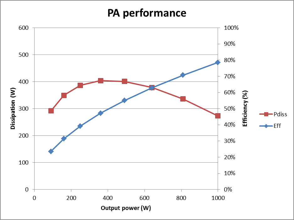
Fig 1 shows the power dissipation in the active device, and conversion efficiency for an ideal Class B power amplifier capable of a maximum power output of 1000W.
Note that the dissipation curve is concave upwards, and that it has a maximum well below maximum power output. Operating at reduced power increases power dissipated unless power output is reduced below 10% of maximum output.
Practical devices do not achieve zero saturation voltage, and this departure from ideal is a significant contribution to reduced efficiency. In valve RF power amplifiers, saturation voltage is often in the range of 10 to 15% of the available supply voltage.
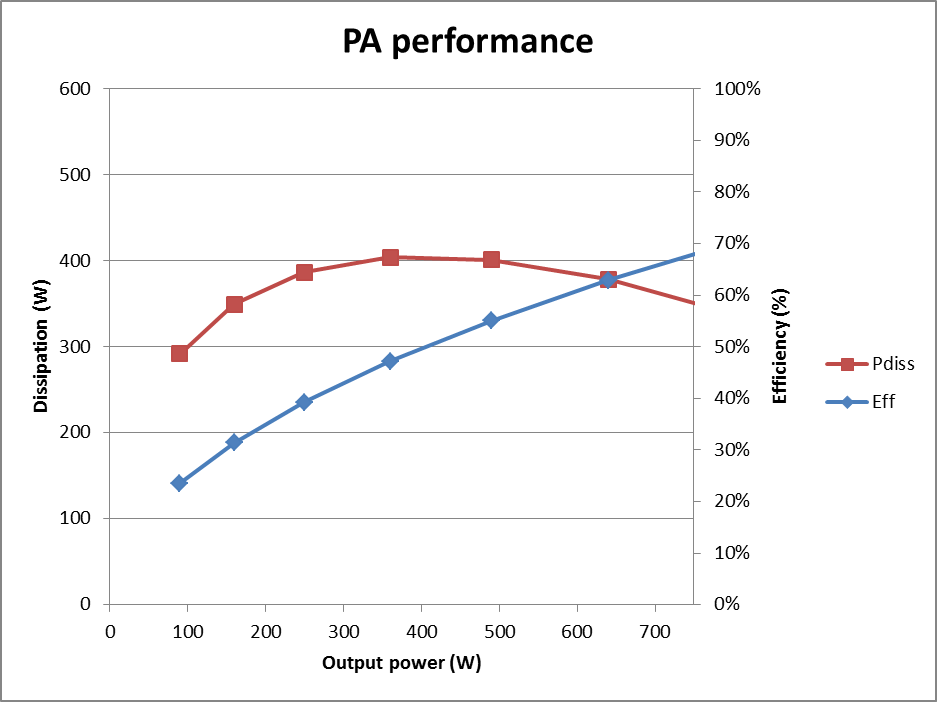 |
Fig 2 shows the effect of saturation voltage on the same PA as in Fig 1. Maximum power is reduced to 750W, and maximum efficiency is lower.
Since we are operating on the lower part of the curves from Fig 1, the point of maximum dissipation is a higher percentage of maximum power output, but the point of maximum dissipation is still well lower than maximum power output. Operating at reduced power increases power dissipated unless power output is reduced below 20% of maximum output.
The AL80B is a practical RF power amplifier. It is not exactly Class B, but the conduction angle is very close to Class B. More importantly, the transfer characteristic is not perfectly linear, both at the top and bottom of the characteristic. The effect of idle current to offset linearity problems at the low end is detrimental to efficiency. Saturation voltage is around 13% of the available DC supply, and that reduces efficiency.
The AL80B is a grounded grid amplifier, and in calculating the conversion efficiency, the cathode drive voltage must be added to the supply to obtain the power input to the valve, and to calculate correct dissipation and anode efficiency.
Sag in the supply voltage will affect the dissipation and efficiency curves.
So that the graphs are comparable, allowance is made for 5% loss in the output circuit in calculating output power at the valve from measured system output power.
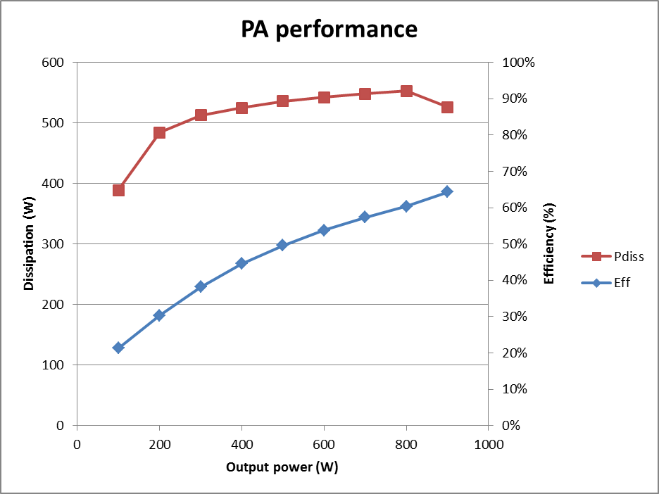 |
Fig 3 shows the anode dissipation and efficiency based on measurements of reduced continuous output of an amplifier initially tuned for 1000W PEP on a pulsed tone waveform.
Though the curve is a little different to the previous cases due to the effects mentioned above, the efficiency curve is still concave upwards, maximum dissipation occurs at reduced output, and power needs to be reduced below about 30% of maximum to obtain lower dissipation than at maximum output.
| Version | Date | Description |
| 1.01 | 13/03/2012 | Initial. |
| 1.02 | ||
| 1.03 |
© Copyright: Owen Duffy 1995, 2021. All rights reserved. Disclaimer.