| OwenDuffy.net |
|
A common configuration for multiband use is a centre fed dipole with some length of open wire feeder, a balun and ATU to deliver a 50Ω load to the transmitter.
This article explores the effect of feedline length and balun transformation ratio on ATU efficiency.
ATU efficiency is sensitive to its load impedance. Achieving efficiency on the lowest bands is the greatest challenge, so this article explores behaviour on 3.6MHz of a T match ATU with 220pF variable capacitors, and inductor Q assumed to be 100. The analysis assumes the balun is ideal.
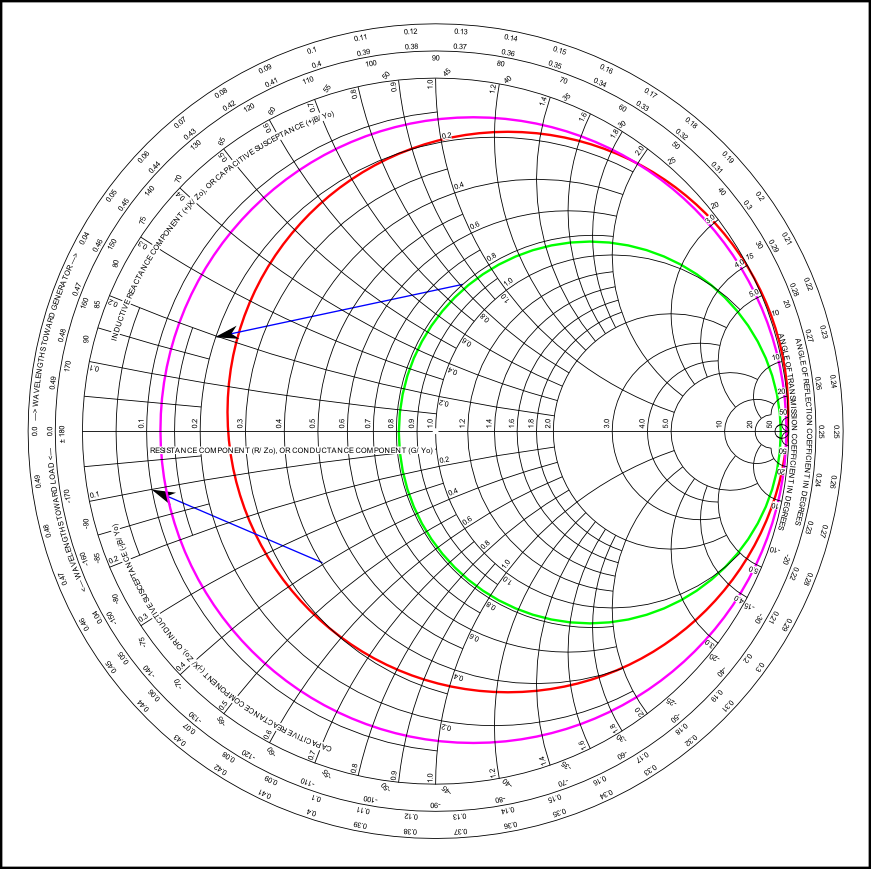
Above is a Smith chart (normalised to 50Ω) showing the approximate bounds of 80% efficiency (1dB loss) for a typical ATU on 3.6MHz in the red circle. Loads outside the red circle have efficiency lower than 80%. Note that loads with low R have low efficiency, and those with larger capacitive reactance are worse. (Click on the image and zoom in for an uncluttered full size version.)
ATUs are traditionally equipped with a 4:1 voltage balun which raises two issues.
The green circle is the lossless 400Ω line SWR circle for a full wave dipole (Z=4200+j0). Note that at all line lengths it is well inside the 80% efficiency contour, but the caution for use of voltage baluns at voltage maxima still applies.
The purple circle is the lossless 400Ω line SWR circle for a G5RV (Z=10-j340). Note that is is almost always outside the 80% efficiency contour, save a small region around Z=9+j300Ω. This range of extreme impedances with reasonable ATU efficiency occurs around 70% of the distance from a current maximum and the next voltage maximum on the 400Ω line. Note that T matches are unlikely to be able to match the extreme impedance found at exactly a voltage maximum if VSWR is very high, but a 30° reduction in length or adding around 150° should bring them in range of an efficient match.
The above suggests that:
For this application, it is hard to look past a 1:1 Guanella (current) balun with high common mode impedance and high differential voltage withstand, and the shortest open wire line that is possible. The current balun is more effective in reduction of common mode current for asymmetric loads than a voltage balun.
If the ATU cannot efficiently match some extreme load cases, increasing the length of the open wire line may resolve the problem. Extreme load cases should not occur in well designed antenna systems, matching is only one of the issues that they create and if they occur, they warrant further investigation.
© Copyright: Owen Duffy 1995, 2021. All rights reserved. Disclaimer.